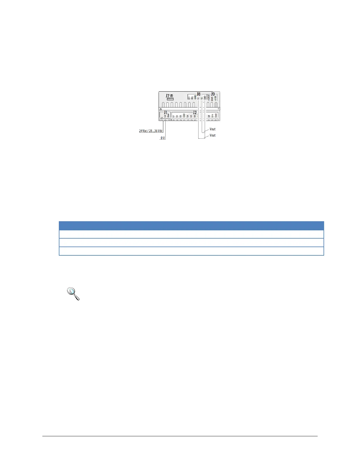
5.7 Analog Outputs
The controller features 0-10Vdc and PWM analog outputs without optical isolation, powered directly by
the controller.
Figure 7 Analog outputs
5.8 Digital Outputs
The controller features digital outputs with electromechanical replays. For ease of installation, the
common terminals of some of the relays have been grouped together. Some relays feature changeover
contacts.
5.9 Cable Length
Note:
A maximum of one terminal (pCOT, pCOI, pGD0, pGD1) can be connected, or two
terminals but without using use the backlighting on display. One version of the
controller features optically-isolated connection to the pLAN network.
The graphic terminal and aria terminal should be always powered with a separate
power supply.
The 21VDC present at +Vterm (J24) can be used to power an external terminal
with a maximum input of 2 W. Only one terminal can be connected (for example
PLD terminal or ARIA terminal) in addition to the one connected to terminal J10.
 Loading...