7.0 Factory Setup
Factory setup is reserved for qualified or factory tech. Changes to factory settings are not
recommended without consulting with factory representative. Factory menu divided into sub
categories including Universal Inputs, Analog Outputs, Digital Inputs, Digital Outputs, HVAC, Load
System Default, and Password.
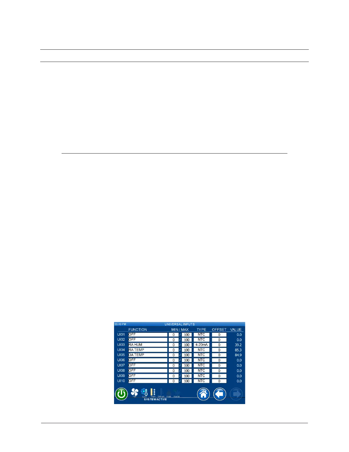
7.1 Universal Inputs
Each UI supports the following functions. For a typical setup, min and max values shall be left at
default of 0 and 100 respectively.
UI[1:10] Description
OFF No function
RA temp Return air temperature
RA hum Return air humidity
MA temp Mixed air temperature
MA hum Mixed air humidity
OA temp Outside air temperature
OA temp Outside air humidity
DA temp Discharge air temperature (after reheat if any)
LPT1 PSI Low pressure transducer for circuit 1 in PSI
HPT1 PSI High pressure transducer for circuit 1 in PSI
LPT2 PSI Low pressure transducer for circuit 2 in PSI
HPT2 PSI High pressure transducer for circuit 2 in PSI
EFan FB[1:4] Evaporator EC fan feedback voltages. Scale: 2-10Vdc.
Water IN Water in temperature
Water out Water out temperature
Air DP Air pressure differential transducer
AVG temp[1:5] Averaging temperature sensors
Cond. Temp1 Condenser temperature 1 used in heatpump
Cond. Temp2 Condenser temperature 2 used in heatpump
User[1:3] User sensor1, sensor2, and sensor3 inputs
Figure 29. Factory setting analog inputs
 Loading...