8.4 BANET over MS/TP For BMS Card add on
Optional add on board is available for BACnet over Master/Slave application.
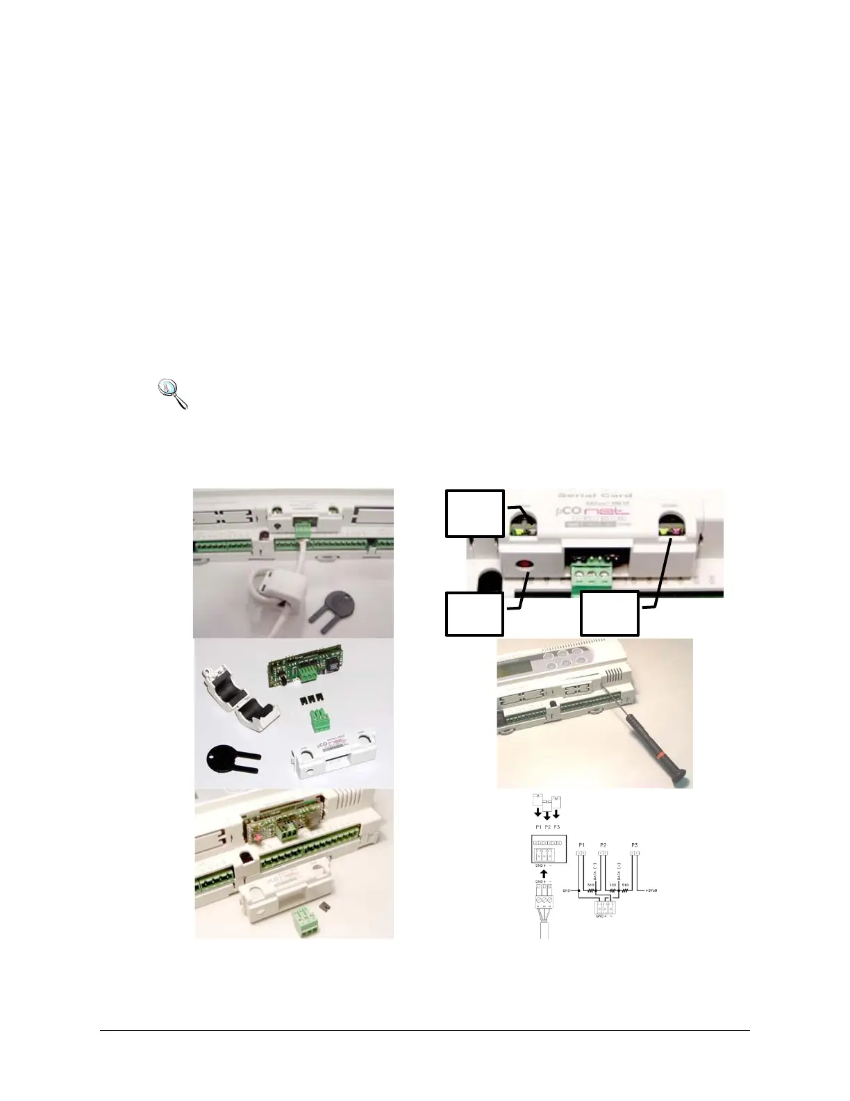
8.4.1 Installation
1. Disconnect the power supply from the controller and remove the “Serial Card” cover.
2. Insert PCOnet card in the plug-in connector, making sure that it is fully inserted and in
contact with the two supports on the controller. As there is little space available, this
operation may be complex: as a result, insert the PCOnet card at an angle then tilt it
back until the connectors’ line up.
3. Insert the required jumpers (see below for the meanings of these).
4. Fit the cover supplied with the PCOnet.
Note: If the device used to read the data from the 485 network is grounded and the
RS232-RS485 converter or the RS485 serial port on the device have functional insulation of
less than 2kV, connector G0 on the controller must be grounded. The board cannot be
installed in direct contact with the metal panel on the electrical panel.
 Loading...