UT-4500 Series C- and Ku-Band Up Converters MN/UT4500.IOM
Appendix A Revision 3
A–4
switched RF outputs – RF Output #1 (priority) and RF Output #2. If Converter #01
faults, Converter #02 backs up the priority channel and IF Signal #2 and RF Signal
#2 are not operational.
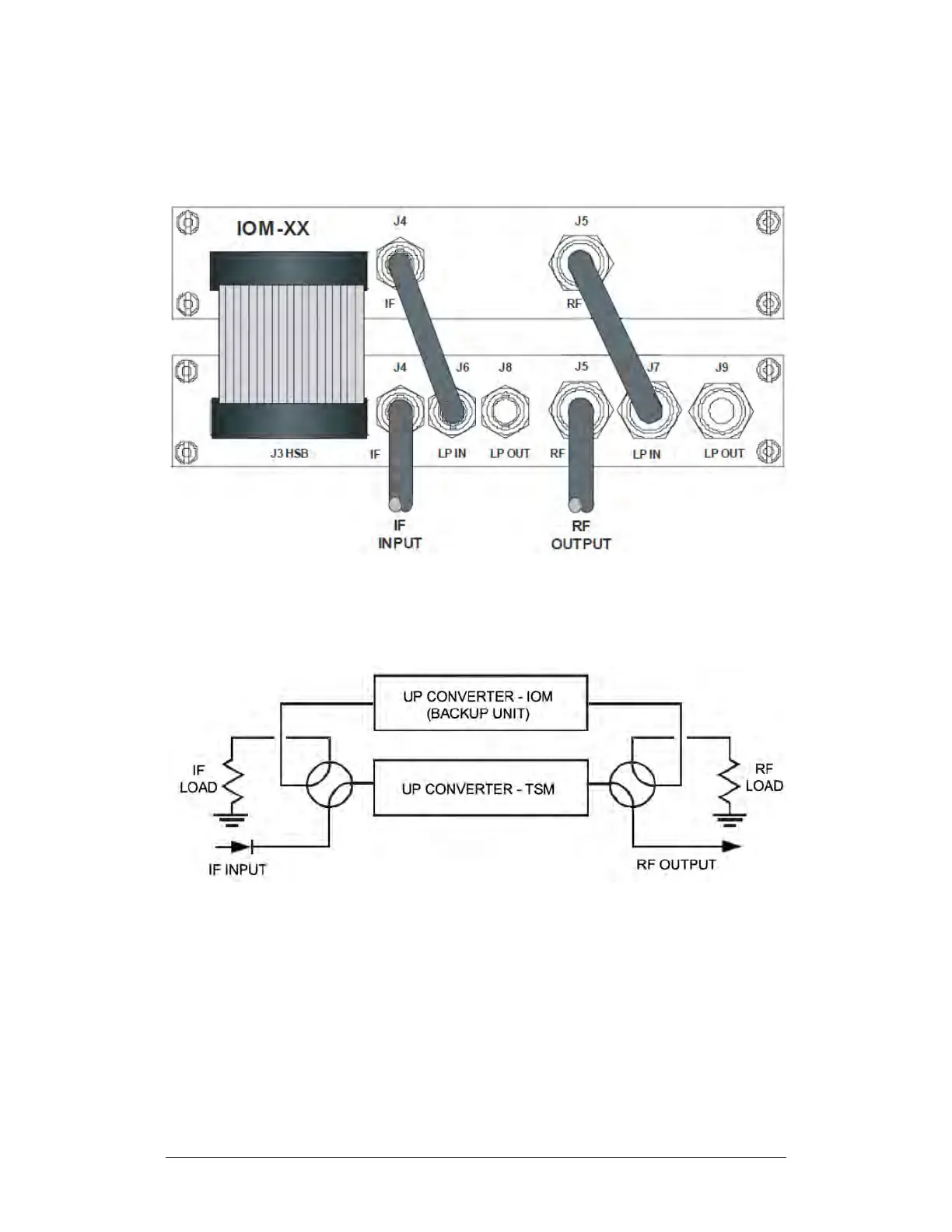
Figure A-1. 1:1 Redundant Configuration –Single Source IF Input (with IOM
and TSM)
Figure A-2. 1:1 Redundant Configuration Diagram – Single Source RF Input
(with IOM and TSM)