E-2 I Appendix
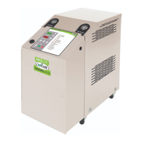
External Interfaces
1TC Input #4 Jumper Positions
Analog Input Jumper
Number
Placement
(4-20mA)
Placement
(0-10V)
Input #4 J1-9
& J1-10
JMP10 OUT OUT
JMP11 OUT IN
JMP13 IN IN
JMP22 IN OUT
NOTE: Signal is not ground-isolated. Customer’s interface must be isolated from ground (or ground loop damage will
result).
1kΩ Minimum input impedance
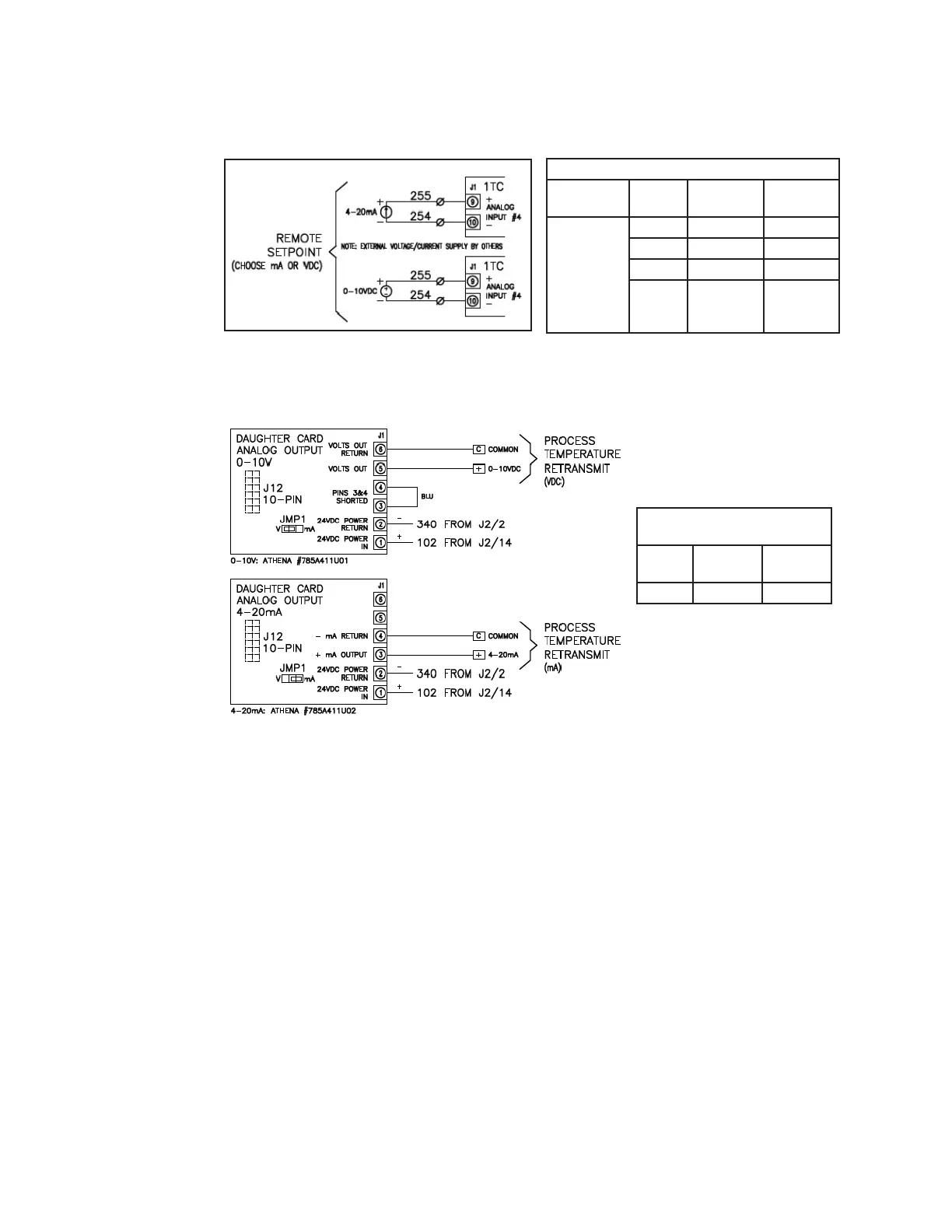
Terminate analog output signal
wire directly on J12 daughter
board connector J1.
Analog Output (J12) Daughter
Card Jumper Positions
Jumper
Number
Placement
(4-20mA)
Placement
(0-10V)
JMP1 Pins 2 & 4 Pins 1 & 2
500Ω Maximum input imped-
ance
Terminate analog output signal
wire directly on J12 daughter
board connector J1.
NOTE: Voltage signal is self-generated by temp controller, but is not ground-isolated. Customer’s interface must be
isolated from ground (or ground loop damage will result).
NOTE: Current signal is self-generated by temp controller but is not ground-isolated. Customer’s interface must be
isolated from ground (or ground loop damage will result).
NOTE: Both analog input and output signals are not isolated from each other in controller. Customer’s interface must
have isolated channels (or reference loop damage will result).
(Continued)
(continued)
 Loading...