Installation I 3-9
3
Installation
Testing the Installation
WARNING: Only qualified personnel should perform this
procedure.
Part of this test requires opening the unit while it is energized. Only qualified
personnel who have been trained in the use of electrical testing devices and in
avoiding the safety hazards involved in safely troubleshooting this type of equip-
ment should perform this test procedure.
1 Turn on the cooling water supply and check for leaks. If any leaks appear, stop the
test and fix the problem before continuing. The cooling water must be at least 25 PSI
or the unit will not function on standard 250° F {121° C} units less than 48kW. Refer
to the appendix for PSI requirements for units with 48kW heaters and 300° F {149° C}
capabilities.
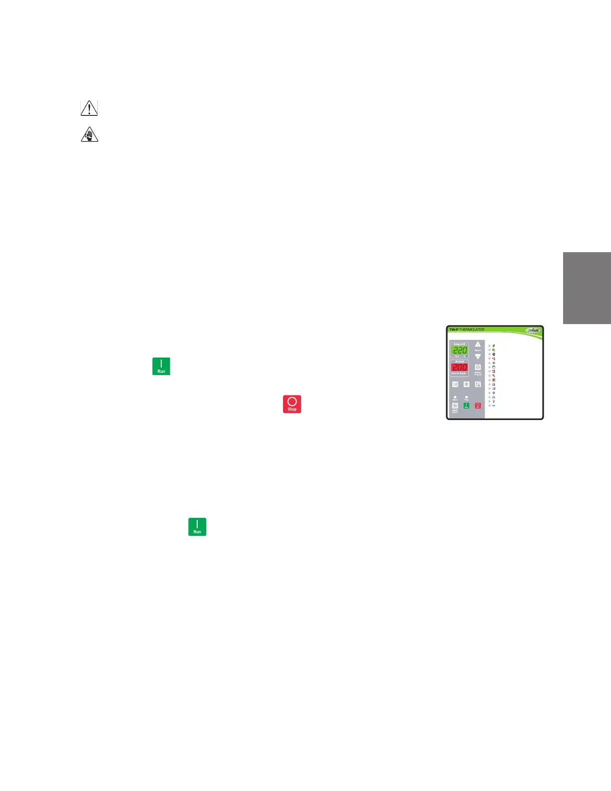
2 Apply power to the unit. The temperature controller display lights up to indicate that
the control has power. All LED segments on the display will light for a few seconds
while the control performs a self-test. The control then displays the software version,
followed by temperature display.
3 Check the rotation of the pump on the TW-S only. (The TW-P has a built-in phase
rotation monitor.) Remove the top access panel and a side panel.
Press the RUN button, and wait until the pump starts. It will take approximately
30 seconds to complete vent cycle.
When the pump starts, quickly press the STOP button and look at the pump
shaft. With a flashlight, verify that the pump rotation matches the direction indicated
on the rotation sticker on the side of the pump motor.
NOTE: If the rotation is incorrect, stop the test and disconnect power to the unit. Open the electrical
enclosure and switch any two of the three power source wires on the incoming power distribution block.
Return to step 2 and check rotation again.
4 Replace the top/side access panel.
5 Press the RUN button
If everything is working correctly:
• The venting and/or pump LED illuminates.
• The unit initiates a 30-second venting sequence. The pump starts automatically
when the venting sequence is over.
• Normal operation begins. The heater turns on if the process temperature is below
setpoint. The cooling valve is activated if the process temperature is above set-
point.
NOTE: If the coolant pressure low LED illuminates, verify that the cooling water supply is connected properly
and that the water pressure is at least 25 PSI or greater except for 48 kw or 300° F {149° C} units. Refer to
the Appendix for more information.
If everything tested correctly, proceed to the Initial Setup instructions on the next
page. If something did not work correctly, refer to the Troubleshooting section of this user
guide.
Mold
Purge
Rapid
Cool
Process
Cool Down
Control Power
Autostart Signal
Pump
Heat
Cool
Coolant Pressure
Temperature Limit
Electrical Phase Error
Heat Error
Process Cool Down
Rapid Cool
Communications
Remote Heat/Cool
Program Mode
Mold Purge
Flow GPM (flash)
Tools Required
r Flashlight
0
 Loading...