Description I 2-9
2
Description
Specifications: TW-P
Specification Notes
Models
TW-P (direct injection)
‡
TW-P (closed circuit)
§
Performance Characteristics
Minimum setpoint temperature °F {°C} 40 {4}
Maximum setpoint temperature °F {°C} 250 {121}, (300 {149} optional)
Minimum operating temperature °F {°C} Approximately 20° {11°} above the cooling water inlet temperature*
Standard cooling valve size inches {mm} 1/4 {6.35} 3/4 {19.05} (varies)
Available pump sizes 0.75, 1, 2, 3, 5, 7.5, 10 Hp {0.56, 0.75, 1.49, 2.24, 3.73, 5.59, or 7.46 kW}
Available heater sizes 6, 9, 12, 18, 24, 36 or 48 kW 9, 12, 18, 24, or 36 kW
Connections to/from process NPT (female) 1.50 inches
Connections in/out cooling water NPT (female) 1.00 inches
Pump Performance - Consult your Conair representative for pump performance characteristics at other operating points.
Pump
3/4 Hp {0.56 kW} 1 Hp {0.75 kW} 2 Hp {1.49 kW} 3 Hp {2.24 kW} 5 Hp {3.73 kW} 7.5 Hp {5.59 kW} 10 Hp {7.46 kW}
Nominal flow gpm {lpm} 50 {189} 55 {208} 75 {284} 85 {322} 100 {379} 120 {454} 150 {568}
Pressure @ nominal flow psi {kg/cm
2
} 20 {1.4} 25 {1.7} 30 {2.1} 32 {2.2} 46 {3.2} 56 {3.9} 65 {4.5}
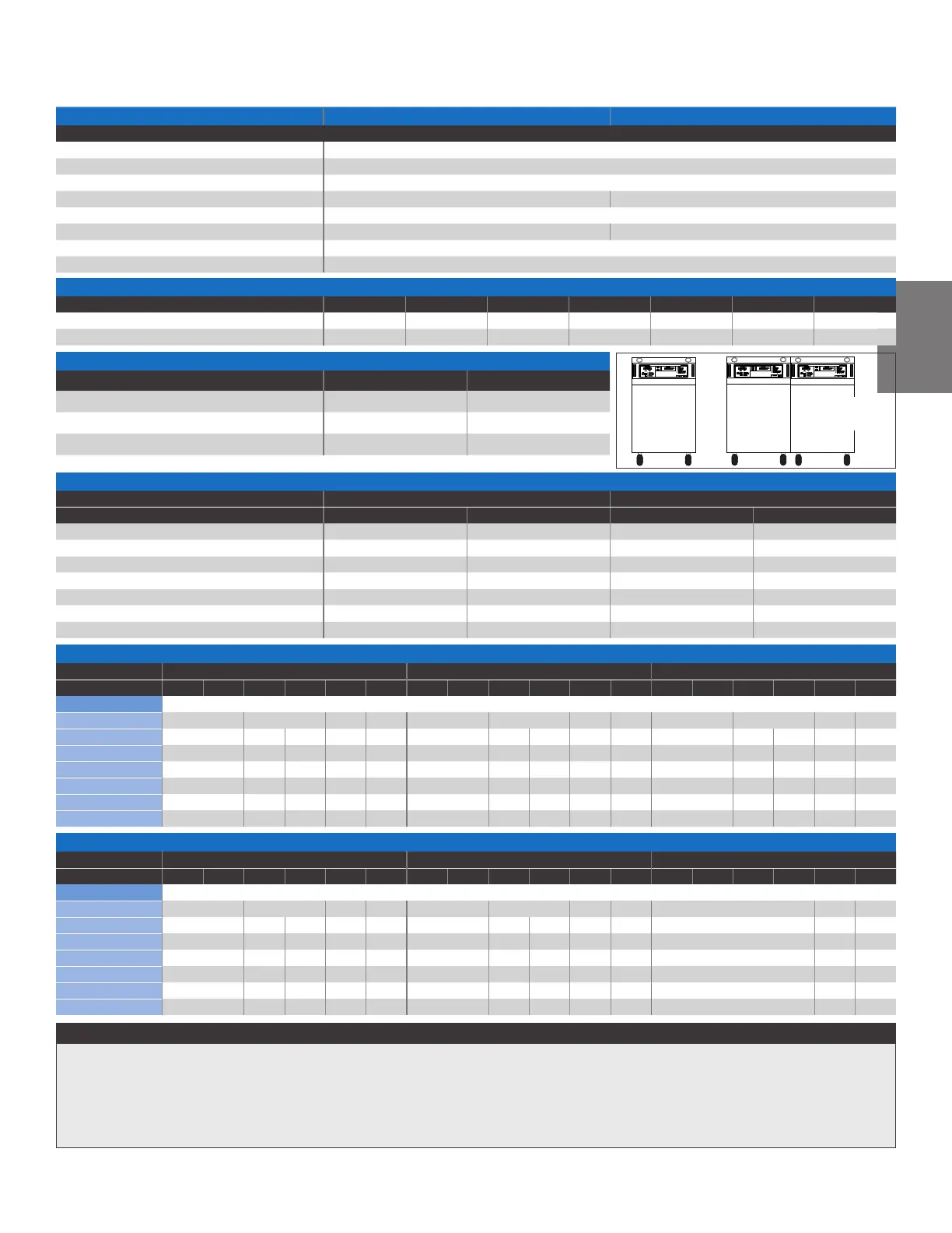
Dimensions inches {mm}
Cabinet Style Single Zone (A)
Dual Zone (B)
†
Height 28.43 {722} 29.00 {734}
Width 14.00 {356} 28.34 {720}
Depth 25.75 {654} 26.06 {662}
Shipping weight ranges lb {kg} Weights vary depending on cabinet size, options,and cooling type (DI or CC).
Single Zone Dual Zone
Pump Minimum Maximum Minimum Maximum
0.75 Hp {0.56 kW} 240 {109} 280 {127} 491 {223} 576 {261}
1 Hp {0.75 kW} 245 {111} 290 {132} 499 {226} 584 {265}
2 Hp {1.49 kW} 248 {113} 298 {135} 515 {234} 590 {268}
3 Hp {2.24 kW} 259 {118} 299 {136} 538 {244} 623 {283}
5 Hp {3.73 kW} 302 {137} 352 {160} 629 {285} 699 {317}
7.5 Hp {5.59 kW} 317 {144} 362 {164} 649 {294} 729 {331}
10 Hp {7.46 kW} 329 {149} 379 {172} 683 {310} 763 {346}
Total Full Load Amps per zone **
Heater 9 kW 12 kW 18 kW
Voltage
208/3/60 230/3/60 380/3/60 400/3/50 460/3/60 575/3/60 208/3/60 230/3/60 380/3/60 400/3/50 460/3/60 575/3/60 208/3/60 230/3/60 380/3/60 400/3/50 460/3/60 575/3/60
Pump size
0.75 Hp {0.56 kW} 25.9 15.0 12.9 10.5 33.4 19.3 16.7 13.5 48.5 28.0 24.2 19.5
1.0 Hp {0.75 kW} 26.8 15.2 15.3 13.3 10.6 34.3 19.5 19.6 17.1 13.6 49.4 28.2 28.3 24.5 19.6
2.0 Hp {1.49 kW} 28.9 16.6 16.7 14.3 11.6 36.4 20.9 21.0 18.1 14.6 51.5 29.6 29.7 25.6 20.6
3.0 Hp {2.24 kW} 31.7 13.4 18.0 15.4 12.5 39.2 22.4 22.3 19.2 15.5 54.3 31.1 31.0 26.7 21.5
5.0 Hp {3.73 kW} 36.3 20.7 18.2 17.7 14.2 43.8 25.0 22.5 21.5 17.2 58.9 33.7 31.2 29.0 23.2
7.5 Hp {5.59 kW} 42.1 24.9 20.5 20.3 16.3 49.6 29.2 24.8 24.1 19.3 64.7 37.9 33.5 31.6 25.3
10.0 Hp {7.46 kW}
50.3 28.9 24.8 24.1 18.9 57.8 33.2 29.1 27.9 21.9 72.9 41.9 37.8 35.4 27.9
Total Full Load Amps per zone **
Heater 24 kW 36 kW 48 kW
Voltage
208/3/60 230/3/60 380/3/60 400/3/50 460/3/60 575/3/60 208/3/60 230/3/60 380/3/60 400/3/50 460/3/60 575/3/60 208/3/60 230/3/60 380/3/60 400/3/50 460/3/60 575/3/60
Pump size
0.75 Hp {0.56 kW} 63.6 36.6 31.7 25.6 93.7 54.0 46.8 37.6 N/A 61.9 49.7
1.0 Hp {0.75 kW} 64.5 36.8 36.9 32.1 25.7 94.6 54.2 54.3 47.2 37.7 N/A 62.3 49.8
2.0 Hp {1.49 kW} 66.6 38.2 38.3 33.1 26.7 96.7 55.6 55.7 48.2 38.7 N/A 63.3 50.8
3.0 Hp {2.24 kW} 69.4 39.7 39.6 34.2 27.6 99.5 57.1 57.0 49.3 39.6 N/A 64.4 51.7
5.0 Hp {3.73 kW} 74.0 42.3 39.8 36.5 29.3 104.1 59.7 57.2 51.6 41.3 N/A 66.7 53.4
7.5 Hp {5.59 kW} 79.8 46.5 42.1 39.1 31.4 109.9 63.9 59.5 54.2 43.4 N/A 69.3 55.5
10.0 Hp {7.46 kW}
88.0 50.5 46.4 42.9 34.0 118.1 67.9 63.8 58.0 46.0 N/A 73.1 58.1
* Lower operating temperatures can be obtained with larger cooling valves.
†
Available in TW-S and TW-P models only.
‡
Direct Inject (DI) cooling injects cooling water directly into the process loop upon
demand.
§
Closed Circuit (CC) cooling injects cooling water into the process loop only during the
initial filling or when make-up water is needed.
** FLA data for reference purposes only. Does not include any options or accessories
on equipment. For full FLA detail for power circuit design of specific machines and
systems, refer to the electrical diagrams of the equipment order and the nameplate
applied to the machine.
Specifications may change without notice. Consult with a Conair representative for the
most current information.
A
B
†
TW-S and
TW-P only
†
 Loading...