Appendix I G-3
Mold Purge Installation Instruction Sheet (continued)
TW-P
12 Attach the two 1/2” pipe nipples to the solenoid valves.
13 Attach the two electrolet elbows to the 1/2” pipe nipples.
14 Attach the two clamp connectors to the electrolet elbows.
15 Cut power cord into two equal lengths.
16 Wire one end of each of the pieces of cable to each of the valves, connecting the wires inside the electrolet elbows.
17 Secure the bushing in the hole in the bottom right corner on the back of the mechanical enclosure and labeled in Detail A.
18 Run the cables through the hole with the bushing just attached, through the hole in the back of the electrical enclosure labeled in
Detail B and into the electrical enclosure.
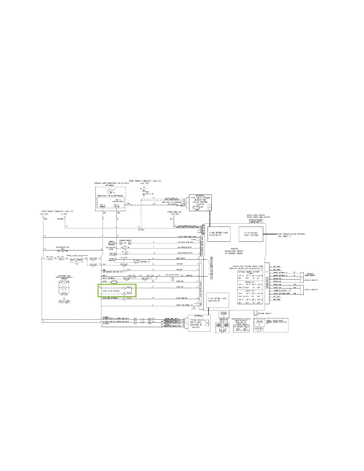
19 Wire the electrical components according to the mold purge option in the control schematic shown below.
Premium Control Electrical Schematic
20 Reinstall all plumbing that was removed during installation.
21 Turn water on and check for leaks. Repair as required.
22 Refer to user manual for mold purge operation. Test unit to confirm operation.
 Loading...