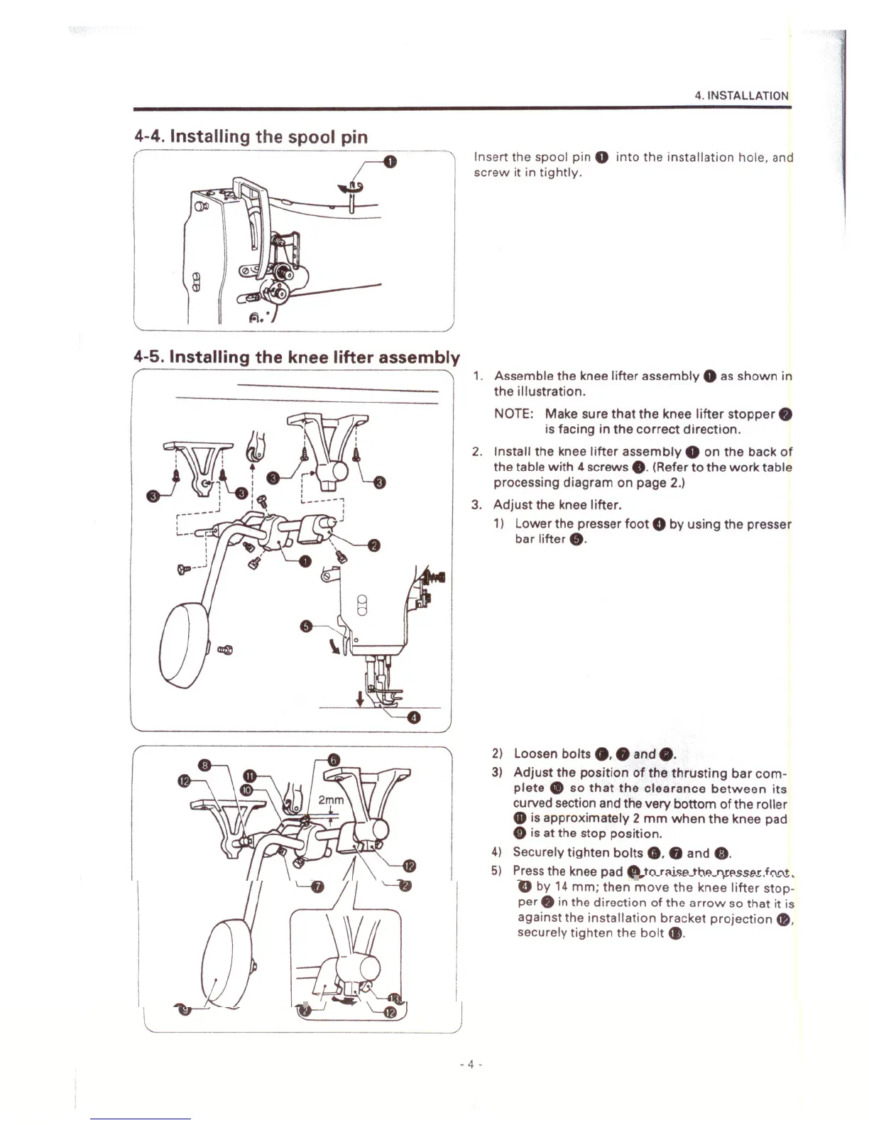
4-4. Installing the spool pin
(
4. INSTAllATION
Insert the spool pin 0 into the installation hole. and
screw it in tightly.
4-5. Installing the knee lifter assembly
- 4 -
1. Assemble the knee lifter assembly
0as shown in
the illustration.
NOTE: Make sure that the knee lifter stopper.
is facing in the correct direction.
2. Install the knee lifter assembly
0on the back of
the table with 4 screws
e.(Refer to the work table
processing diagram on page 2.)
3. Adjust the knee lifter.
1) Lower the presser foot
eby using the presser
bar lifter
e.
2) Loosen bolts ••• and O.
3) Adjust the position of the thrusting bar com-
plete ., so that the clearance between its
curved section and the very bottom of the roller
• is approximately 2 mm when the knee pad
CD is at the stop position.
4) Securely tighten bolts ••• and
G.
5) Pressthe knee pad CD to raise the presser foot
eby 14 mm; then move the knee lifter stop-
per. in the direction of the arrow so that it is
against the installation bracket projection ••
securely tighten the bolt •.