2. Module Nomenclature
ADI16-4(USB)
9
2.
Module Nomenclature
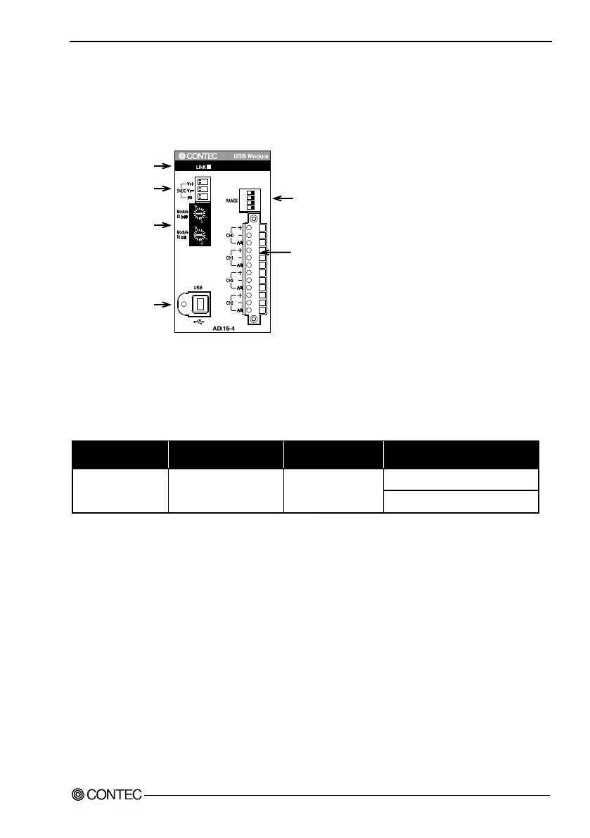
Figures 2.1 shows the names of module components.
In the figures, the indicated switch settings represent factory settings.
Figure 2.1. Nomenclature of Module Components < ADI16-4(USB) >
*1 When you use the module in a noisy environment or are nervous about noise, ground the module
(using a M3 screw).
Table 2.1. List of Status LED Functions
Name Function Indicator color LED indicator
LINK status USB communication states GREEN
ON : Communication established
OFF : Communication unestablished
LI
NK
St
at
us
LE
D
An
al
og
Inp
u
t
CH
0
-
CH3
R
an
g
e
se
tt
i
ng
S
W
M
odu
le I
D
US
B Po
rt
+5
VD
C
Inp
ut
0
2
4
5
6
7
9
A
C
D
E
F
8
0
2
4
5
6
7
9
A
C
D
E
F
8