3. Setup
20
ADI16-4(USB)
Connecting to an External Device
Signal Layout
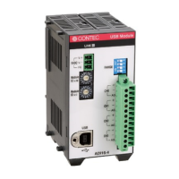
The Module can be connected to an external device using a 12-pin (1 group) connector that is provided
on the Module face.
Figure 3.5. Signal Layout on the Interface Connector < ADI16-4(USB) >
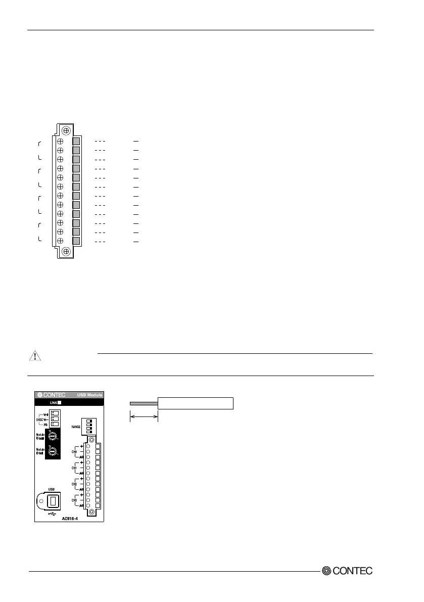
Connection Method
When connecting the Module to an external device, you can use the supplied connector plug. When
wiring the Module, strip off approximately 9 - 10 mm of the covering for the cable, and insert the bare
wire by pressing the orange button on the connector plug. Releasing the orange button after the wire is
inserted fixes the cable. Compatible wires are AWG 28 - 16.
Removing the connector plug by grasping the cable can break the wire.
Figure 3.6. Connecting an Interface Connector and Connectors That Can Be Used
1
2
11
10
9
8
7
6
5
4
3
2
1
C
H
0
[
+
]
C
H0
[-
]
A
G
C
H1
[
+
]
C
H1
[-
]
A
G
CH
2
[
+
]
C
H2
[
-
]
AG
CH3
[+
]
C
H
3
[
-
]
A
G
A
na
l
og
In
pu
t
0
ch
[+
]
A
n
al
og
In
pu
t
0
c
h
[-
]
An
a
l
o
g
G
r
o
u
n
d
A
na
l
og
I
n
put
1ch
[+
]
An
alog
In
put
1ch
[-
]
A
na
lo
g
G
ro
u
nd
A
n
a
l
o
g
In
p
u
t
2
c
h
[
+
]
A
n
a
l
o
g
In
p
u
t
2
ch
[
-
]
An
alog
Gr
oun
d
Ana
log
In
put
3ch
[+
]
A
n
a
l
o
g
I
np
u
t
3
c
h
[
-
]
A
n
a
l
o
g
G
ro
u
n
d
C
H
0
CH1
C
H
2
CH3
+
-
AG
+
-
A
G
+
-
AG
+
-
AG
- Connector used:
3.81mm pitch 12
pi
n type of r
ated current 8A
M
C-1,5/1
2-GF-3,81 (made by P
hoenix Cont
act Corp.)
9 - 10mm
- Compatible plug
:
Front-ope
rable spring gauge type
FRONT-MC 1,5/12-STF-3,81 (made
by Phoenix Contact Corp.)
Compat
ible wires : AWG 28 - 16
0
2
3
4
5
6
7
9
A
C
D
E
F
8
0
2
3
4
5
6
7
9
A
C
D
E
F
8