7. Product Specification
ADI16-4(USB)
57
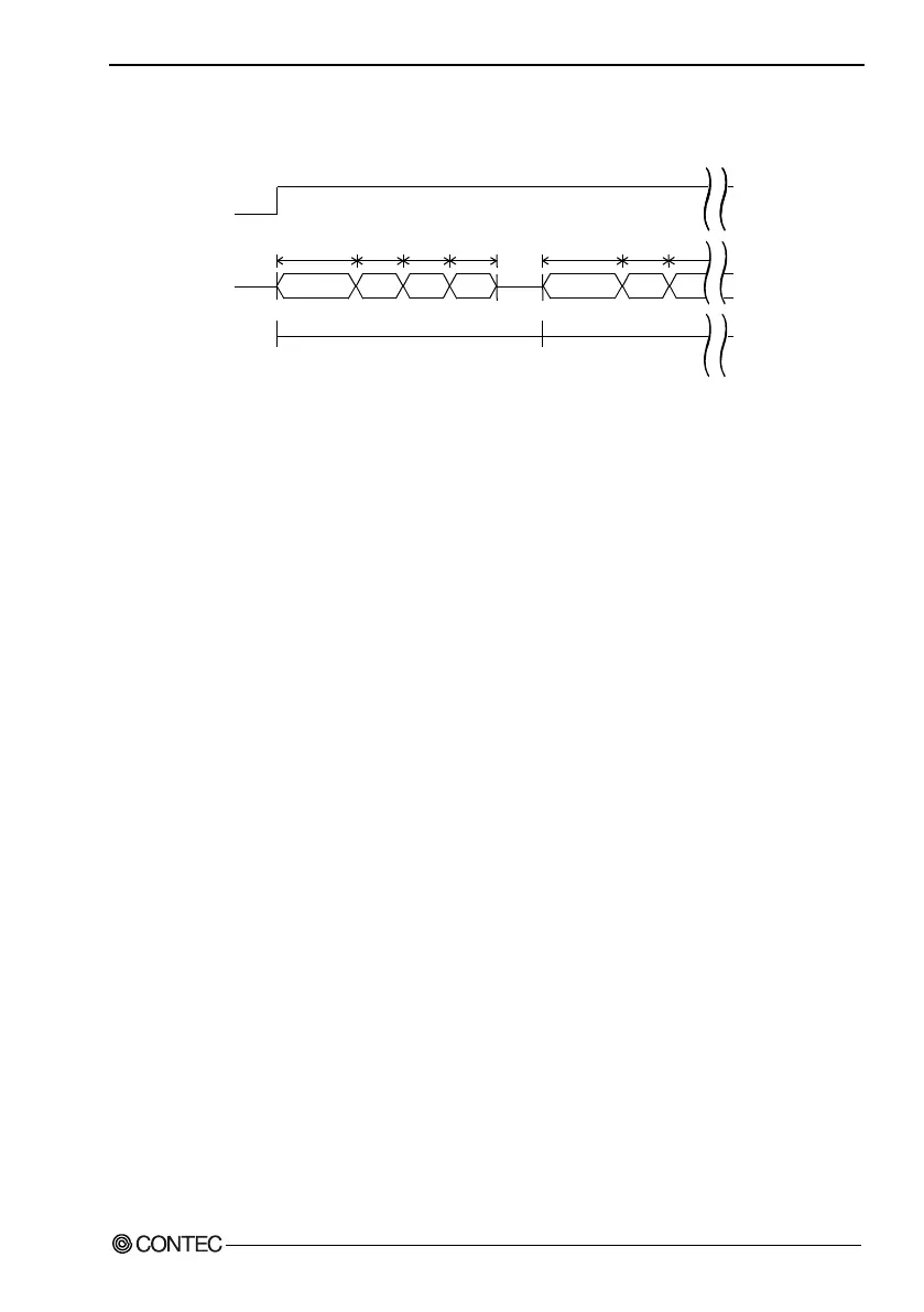
Timing Chart
[C1]: 20µsec
[C2]: Voltage input 10µsec / Current input 40µsec
Figure 7.2. Timing Chart
Setting
Sampling timer value: 1000
µ
sec
Modules used: ADI16-4(USB) [ID=0] conversion channel 0ch - 3ch
ADI16-4(FIT)GY [ID=1] conversion channel 0ch - 3ch
Operation
1. Start timer with the sampling timer set in ADI16-4(USB)
2.
At rise edge of internal sampling clock, output conversion start command to ADI16-4(USB) and at
the end of data input, output A/D conversion start command to ADI16-4(FIT)GY.
Sampling timer
Processing
Device
C1 + C2 C2 C2 C2
0ch 1ch 2ch 3ch
0ch 1ch 2ch
C1 + C2 C2 C2
A/D conversion ID=0(module)
A/D conversion
ID=1(expansion)
Data input