3. Setup
ADI16-4(USB)
11
3.
Setup
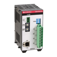
Connection-Overall Diagram
This is connection-overall diagram. Please reference to this page for actual
Figure 3.1. Connection-Overall Diagram
Setting a Module ID
The host computer distinguishes and keeps track of the modules of same model by assigning Module
IDs to them. Factory settings “00” can be used when only one module per model is connected to one
computer.
Each module should be assigned a unique Module ID in the range of 00 - 7Fh when several modules
with the same model are being connected.
There are two rotary switches, moreover, “x16” and “x1” represent high bits and low bits of Module ID
respectively.
Figure 3.2 Setting a Module ID
0
2
4
5
6
7
9
A
C
E
F
8
0
2
4
5
6
7
9
A
C
E
F
8
0
2
4
5
6
7
9
A
C
E
F
8
0
2
4
5
6
7
9
A
C
E
F
8
A
DI1
6-4
Dev
ice
I
D
0
4
7
3
6
2
5
1
RA
NGE
C
H0
CH
1
CH
2
CH
3
+
-
AG
+
-
A
G
+
-
A
G
+
-
AG
Softw
are
In
stallation
(
Pag
e 1
3)
Connecting to a PC
(Page 16)
Mou
ntin
g on a DIN Rail
(
Pag
e 31)
Co
nnecting to an External
Dev
ice (Page 20)
Con
necting
with Expansion
Accessories (Page 45)
Module ID 00h
[Factory Settings]
Module ID 12h
[Factory Settings]
Module
ID(x16)
Module
ID (x1)
[0]
[0]
Module
ID(x16)
Module
ID (x1)
[1]
[2]
0
1
2
3
4
5
6
7
9
A
C
E
F
8
0
1
2
3
4
5
6
7
9
A
C
E
F
8
0
1
2
3
4
5
6
7
9
A
C
E
F
8
0
1
2
3
4
5
6
7
9
A
C
E
F
8