3. Setup
28
ADI16-4(USB)
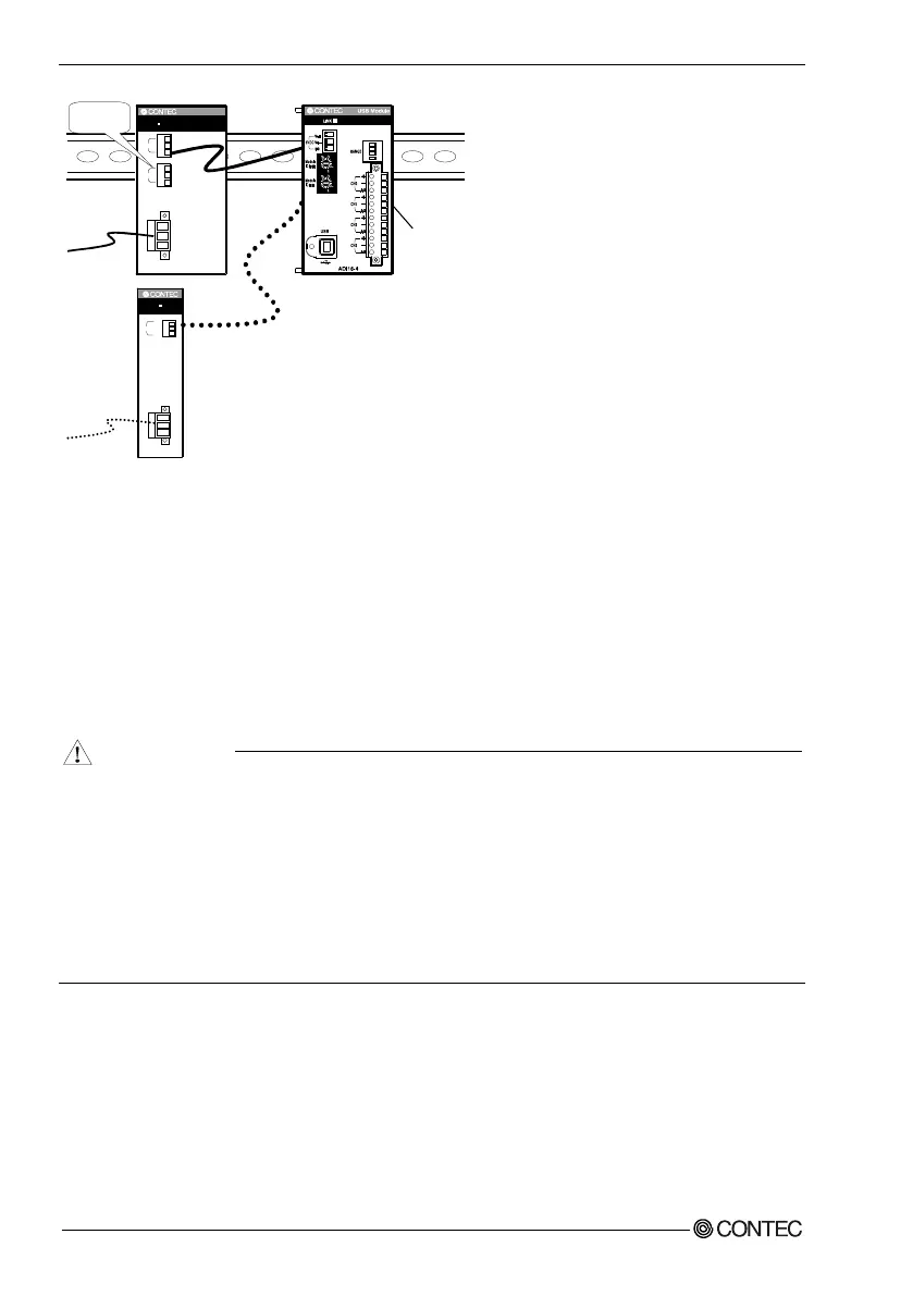
Figure 3.12. Optional power supply
For the power supply for installation on a DIN rail, use the connector MC1,5/3-ST-3,5 (Phoenix
Contact).
Connecting method
- To connect the external power supply and USB cable to the unit, take the steps below:
(1) Connect the external power supply connector to supply power to the USB module.
(2) Use the USB cable to connect the USB module to the PC.
- To remove the external power supply and USB cable from the unit, take the steps below:
(1) Unplug the USB cable.
(2) Remove the external power supply connector to stop power supply to the USB module.
- To use the AC adapter, connect it to the USB module first, then plug the AC adapter's connector
into a wall outlet.
- When the USB module is not used, leave the AC adapter unplugged.
- Continuously using the AC adapter heated affects its life.
- Use the AC adapter not in a closed place but in a well-ventilated place not to be heated. The AC
adapter heats up itself when loaded heavily. If the AC adapter is exposed to high temperature or
used continuously, you should keep the load at about 80% of the maximum load (at 1.6 A for the
POA200-20-2).
AC
In
pu
t
DC
In
pu
t
MC
1
,5
/
3-S
T-3,5
(
Pho
e
ni
x C
ont
act)
PO
W-A
D13
P
OW
E
R
V
o+
Vo
-
FG
5
VD
C
Vo+
Vo
-
FG
5VD
C
85
-13
2VA
C
AC
(N)
AC(L
)
FG
5VDC
V
o+
Vo-
FG
Vo
+
Vo-
FG
10*
30VDC
P
OW-DD10
PO
WER
2
O
u
tp
u
t
0
2
4
5
6
7
9
A
C
E
F
8
0
2
4
5
6
7
9
A
C
E
F
8