*
M’Ax User Guide 103
Issue Number: 4
Appendix F Motor Thermal-
Overload Protection
If the output current of the Drive is to be de-rated, follow the
instructions in this Appendix after following
De-rating the Drive on
page 40.
Being suitable for most applications, the default motor-protection
settings produce the following:
• AnalarmisproducedbytheDrivewhenthemotorwindingsare
calculated to be at their maximum safe working temperature
(defined by the motor) and the motor current is at least 110% of the
rated continuous current of the motor (also defined by the motor).
• When the motor is calculated to be in thermal overload, the
SLM
alters its current-scaling to limit the motor current to 105% of the
rated continuous motor current.
• If the calculated value of temperature is not reducing (ie. demand is
not reduced), the Drive will trip 10 seconds after the alarm is
produced (trip code:
I2t.AC). (10 seconds is the default value of 4.54
Thermal-overload time to trip.)
If required (after having followed the instructions in Appendix
D Optimising the Dynamic Performance on page 93), follow the
instructions in this Appendix in order to achieve the following:
• Apply a motor thermal-overload alarm signal to the controller.
• Adjust the overload alarm to operate at a lower motor current. This
allows the controller sufficient time to reduce the demand before the
motor becomes overheated (e.g. to allow for a process cycle to
finish)
• Increase the limit-level for the motor current during thermal overload
so that the
SLM does not alter the current scaling
• Adjust the time delay after which the Drive will trip (trip code:
I2t.AC)
A motor thermal-overload alarm is indicated by parameter
10.17 Motor
[I
2
t] overload alarm indicator becoming set at 1 and the display (version
_
AN) indicated OuL.
Before making any adjustments to the motor-
protection parameters, ensure that the intended level of
protection will be suitable for the motor. Failure to
observe this may result in fire.
F.1 Assigning a digital output
1. Identify an unused digital output.
2. Refer to the following table to identify which selection parameter to
adjust for the digital output to be used:
3. Set the related selection parameter at
10.17.
4. By default, the output state will become logic 1 (+24V) when the
alarm occurs. If this needs inverting, set the related invert parameter
at
1.
5. Perform the following, as appropriate:
Version _AN
Initiate the save operation by setting parameter XX.00 at 1000.
Execute the operation by performing either of the following:
• While the display is in Edit mode, press at the same time:
•Setparameter
10.38 at 100 (via serial communications)
Version _SL
Version _AN
(if required)
Ensure the Drive is disabled by checking that the
Hardware enable
contact is open or that parameter 6.15 is set at 0, then perform either
of the following:
• Initiate thestore operation by setting parameter
0.50 at 2 (Prog).
Execute the operation by setting parameter
10.38 at 100.
•Set
11.67 Flash update enable at 1.
6. Version _
AN: To use the saved values after the next power-up,
ensure parameter
0.50 is set at no (0). Do not change the setting
while following the remainder of this Appendix.
7. Version _
SL: To use the stored values after the next power-up,
ensure parameter
0.50 is set at 4 (boot2). Do not change the setting
while following the remainder of this Appendix.
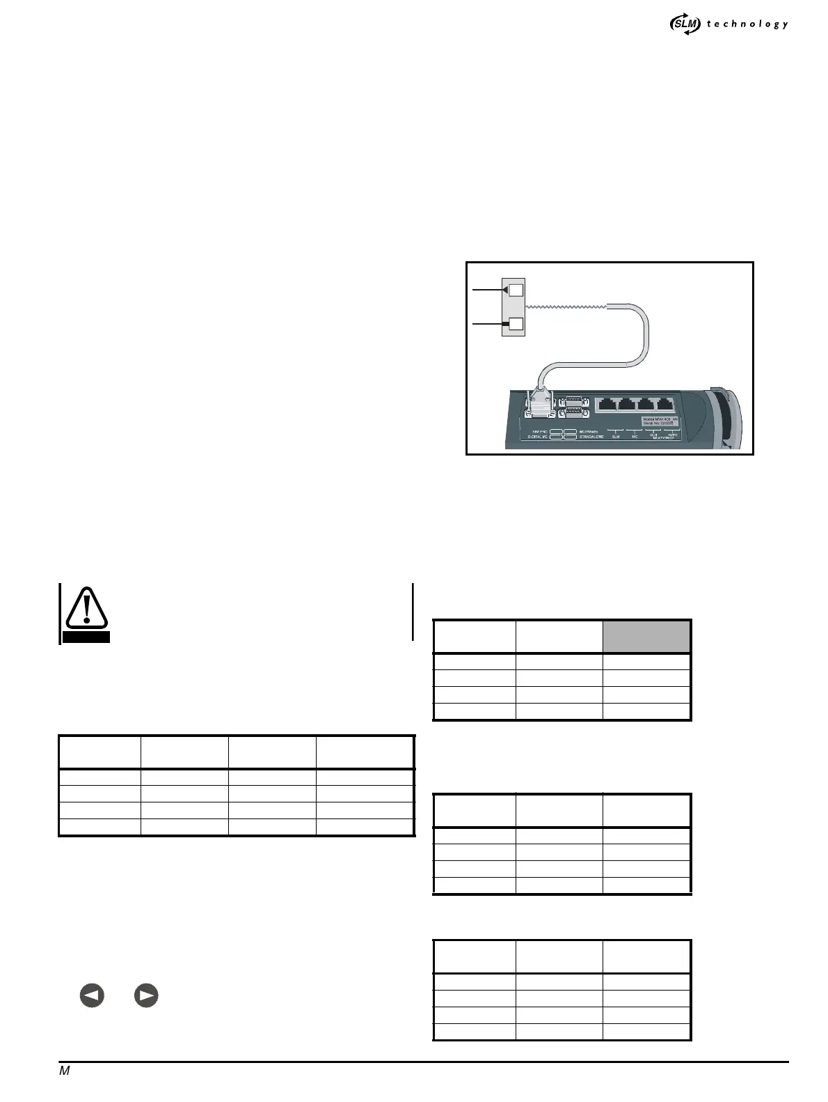
Figure F-1 Signal connections for the motor thermal-overload
alarm (these are additional to those shown in Figures 2–3 to 2–12)
Example
A Drive is to be remotely controlled by a system controller or PLC
supplying quadrature AB signals. A supply interlock is to be used. The
motor protection input of the controller requires logic state
0 to initiate
the alarm.
1. RefertoFigureF-2andusethefollowingtabletofindoutwhich
digital outputs are not in use:
2. Select one of the unused digital outputs, for example
Digital output
4
, and make an appropriate connection to it.
3. Use the following table to find out which selection parameter to
adjust:
4. Set parameter
8.74 at 10.17.
5. Use the following table to find out which invert parameter to adjust:
Digital output DIGITAL I/O
Selection
parameter
Invert parameter
1 5 8.71 8.61
2 4 8.72 8.62
3 3 8.73 8.63
4 2 8.74 8.64
CAUTION
and
Digital output
DIGITAL I/O
terminal
1 5 Unused
24Used
33Used
4 2 Unused
Digital output
DIGITAL I/O
terminal
Selection
parameter
1 5 8.71
2 4 8.72
3 3 8.73
4 2 8.74
Digital output
DIGITAL I/O
terminal
Invert
parameter
1 5 8.61
2 4 8.62
3 3 8.63
4 2 8.64
DIGITAL I/O
11
Digital output
0V COMMON