*
78 M’Ax User Guide
Issue Number: 4
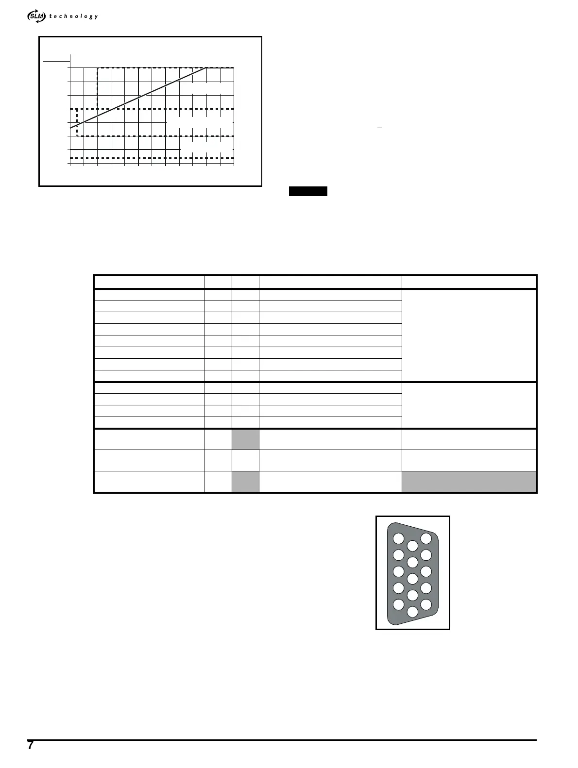
Figure A.1 Digital-input characteristic for the Drive (solid line) and
IEC1131-2 standard (broken lines)
Hardware enable
Hardware enable
is a positive-logic input having the specification given
above. Time delays are as follows:
Enable time: <250
µs
Disable time: <500
µs
A.4 Digital outputs
Logic sense: Positive
Output voltage: –0 ~ 24V +
10%
Isolation: optical
Maximum output current: 100mA, short-circuit protected at 450mA
Update time: 500
µs
Capacitive-load tolerance: 0.1
µF
For clarity in the following lists, the pins are not all shown in
numerical order.
A.5 Functions of the terminals
Figure A.1 Male D-type connector pin locations (as seen from the
top of the Drive)
−
5
0
5
10
15
20
25
30
0 1 2 3 4 5 6 7 8 9 10 11 12
V
IN
(V)
I
IN
(mA)
ON region
Transition region
OFF region
NOTE
Name Pin I/O Function Specification
Digital input 1 10 I RUN
(See Digital inputs earlier in this
Appendix.)
Digital input 2 9 I REVERSE SELECT
Digital input 3 8 I JOG FORWARD
Digital input 4 7 I FORWARD LIMIT
Digital input 5 1 I REVERSE LIMIT
Digital input 6 6 I RESET
Digital input 7 13 I PRESET SELECT BIT-0
Digital input 8 12 I PRESET SELECT BIT-1
Digital output 1 5 O DRIVE RUNNING
(See Digital inputs earlier in this
Appendix.)
Digital output 2 4 O AT ZERO SPEED
Digital output 3 3 O ALARM
Digital output 4 2 O AT SPEED
0V COMMON
11
14
For use with all the I/O on this circuits
0V COMMON must not be
interchanged with 0V
24V user supply 15 O 24V supply for external control circuits
(See 24V user supply earlier in this
Appendix.)
Cable shields Shell
Conect all the cable shields to the
connector shell
1
6
8
11
7
15
14
13
12
9
10
4
5
2
3