*
M’Ax User Guide 79
Issue Number: 4
STANDALONE
Pulse reference inputs
Terminate pulse reference inputs at the Drive by connecting across the
related input terminals a resistor whose value equals the characteristic
impedance of the cable that is being used. When more than one Drive is
connected to a pulse reference link, a terminating resistor is required
only at the last Drive on the link.
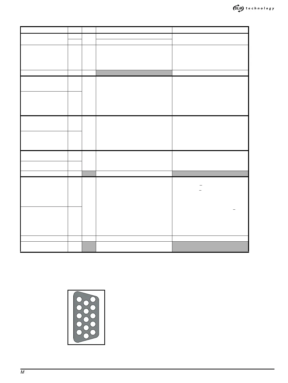
Figure A.2 Male D-type connector pin locations (as seen from the
top of the Drive)
Name Pin I/O Function Specification
SLM-and-user back-up
supply
1
I
+24V input
(See Types of back-up supplies on page
17.)
2OV
0V COMMON
11
14
I
For use with:
Hardware enable
Direction input Quadrature B input
Frequency input Quadrature A input
24V user supply
OV COMMON must not be interchanged
with 0V
Hardware enable 3 I
(See Digital inputs on page 77.)
Direction input
Quadrature B input
Reverse Frequency
4
I
Tri-function input, used for:
Specifying direction when pins 10 and 5
are used for frequency input (default
function)
Quadrature B input when speed is
controlled by quadrature AB signals
Reverse frequency input when speed is
controlled by a pulse directional signal
2wireEIA485
Connecting cable: Shielded twisted pair
Unit load: 3.5
Line termination resistor: (see below)
Line bias resistors: 12
Ω
Direction input \
Quadrature B input \
Reverse Frequency \
9
Frequency input
Quadrature A input
Forward Frequency
10
I
Tri-function input, used for:
Frequency input (direction applied to pins
4,9)
Quadrature A input when speed is
controlled by quadrature AB signals
Forward frequency input when speed is
controlled by a pulse directional signal
2wireEIA485
Connecting cable: Shielded twisted pair
Unit load: 3.5
Line termination resistor: (see below)
Line bias resistors: 12
Ω
Frequency input \
Quadrature A input \
Reverse Frequency \
5
Touch-trigger input
6
I Touch-trigger function
Positive-logic digital input
Voltage range: 0~30V
Response time (on and off): 200ns
Optically isolated from all other signals
Touch-trigger input \ 7
(No connection) 8
Do not use
High-precision analog
input
12
I Available only in version _
AN
Differential analog input
Voltage range: +
10V
Voltage offset: <
150µV (equivalent to 17-
bit resolution)
Resolution: 16-bit (in speed mode)
Sample time: 250
µs
Maximum common-mode voltage: +
25V
relative to 0V COMMON
Linearity: 400ppm (full-scale)
Full-scale accuracy before the analog input
is calibrated: 1%
Input impedance: 20k
Ω
High-precision analog
input \
13
24V user supply 15 O 24V supply for external control circuits (See 24V user supply on page 77.)
Cable shields Shell
Connect all the cable shields to the
connector shell
1
6
8
11
7
15
14
13
12
9
10
4
5
2
3