*
92 M’Ax User Guide
Issue Number: 4
Appendix D Optimising the
Dynamic
Performance
D.1 Speed-loop parameters
The dynamic performance during operation in speed control is controlled
by the following parameters which are adjusted during commissioning of
the system:
3.10 {0.13} Speed-loop proportional gain
3.11 {0.14} Speed-loop integral gain
3.12 {0.15} Speed-loop derivative gain
The default values of these speed-loop PID-gains parameters can be
used for most applications.
Table D.1 Ranges of values
The default values depend on the motor being used.
Inappropriate values entered in the parameters for the
speed-loop PID gains can cause the control system to
become unstable.
Current-loop bandwidth
If any mechanical resonances lie within the current-loop bandwidth of
theDrivetheycangiverisetotorqueoscillationsresultinginthe
following effects, for example:
•Noisymotor
•Vibration
• Instability
• Over-current trips
(Inertia mismatch and flexible couplings are prone to introducing such
resonances.)
Torque oscillations can be minimised by adjusting the current-loop
bandwidth of the Drive in addition to the PID gains.
PID-gains buffers
The PID-gains parameters are held in the Drive, along with a copy of
each held in a buffer in the SLM for use by the speed loop.
Adjustment of the PID gains is made by changing the values of the
parameters held in the Drive (eg.
3.10 {0.13}, 3.11 {0.14}, 3.12 {0.15})
and updating the SLM either concurrently or subsequently.
In addition to the set of PID gains already described and which are
duplicated in Menu 0, two addtional sets of gains are available only in
Menu 3. Rapid selection can be made between these three sets while
the motor is running (see Gain sequencing on page 96).
Methods of adjusting the PID gains
For a practical approach to optimising the dynamic performance, see
Adjusting the speed-loop gains (which follows).
For a simple approach, see Specifying shaft stiffness and load inertia on
page 93.
D.2 Adjusting the speed-loop gains
ThisprocedurerequirestheDrivetobeoperatedinspeedcontrolduring
adjustments.
Higher gains result in the following:
• Greater shaft stiffness
• Greater peak currents with increased possibility of the Drive tripping
on over-current
• Smaller stability margin
If required, see also Gain sequencing on page 96.
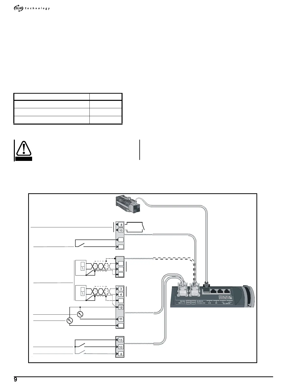
Figure D-1 Signal connections for adjusting the speed-loop gains
Parameter Range
3.10
{0.13} Speed-loop proportional gain 0 ~ 0.3000
3.11 {0.14} Speed-loop integral gain 0~20.00
3.12 {0.15} Speed-loop derivative gain 0 ~ 0.1000
CAUTION
MC/EIA485
Hardware enable
24V user supply
Hardware enable
Status
relay
Drive monitoring
11
3
STANDALONE
RUN
DIGITAL I/O
24V user supply
RESET
Digital input 1
Digital input 6
0V COMMON
SPEED
0V
Analog output 1
Analog output 2
SIM ENC
15
Cable shields
Standard-precision
analog input
CURRENT
(TORQUE)
13
12
14
9
High-precision
analog input
_SL
_MD
_AN
Speed reference
(±10V)