Midi-Maestro and Maxi Maestro Drive
8
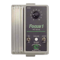
Motor connections
Normally the motor should be connected directly to
pins 17 and 18 of the power connector as shown in
figure 10.
Ext Drive braking resistor
Ext Drive braking resistor
L3
L2
L1
Earth (Ground)
-DC
20
21
22
23
24
25
Power connector
19
20
18
17
16
M2
M1
+DC
Figure 10 Normal motor connections
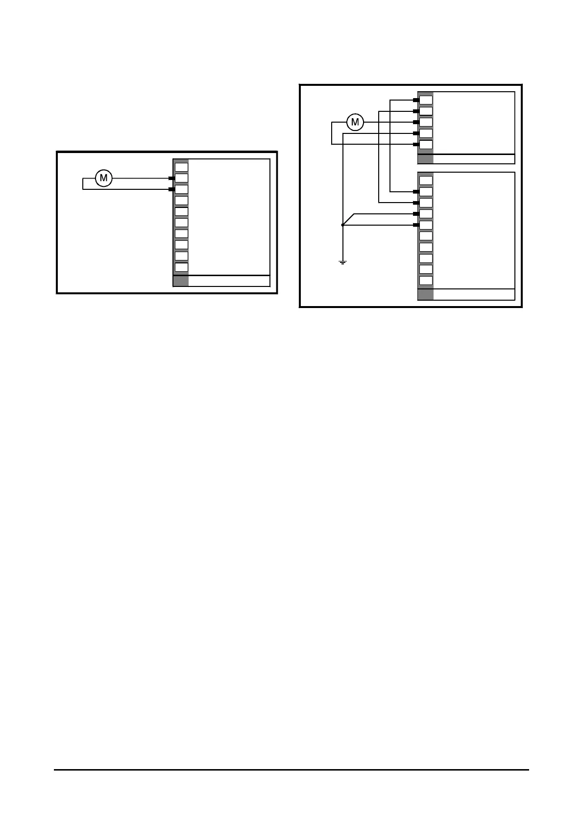
When any of the following conditions apply, a choke
should be connected to each Drive output as shown in
Figure 11 and Figure 12
• When a Midi-Maestro Drive is being used and
the motor inductance is less than 2mH
• When a Maxi-Maestro Drive is being used and
the motor inductance is less than 3mH
• During emergencies, the user short-circuits
the motor connections
• High frequency switching noise is troublesome
• The motor overheats (irrespective of motor
inductance)
When a choke is fitted, pin 17 should be connected to
terminal 1 of the choke and pin 18 should be connected
to terminal 2 of the choke.
Ext Drive braking resistor
Ext Drive braking resistor
L3
L2
L1
Earth (Ground)
-DC
20
21
22
23
24
25
Power connector
19
20
18
17
16
M2
M1
+DC
1
2
3
4
5
Choke (optional)
Figure 11 Motor and choke connections
The two cables between the Drive and the choke are a
source of noise. The cables should be kept as short as
possible (300mm is recommended).
Terminal 3 of the choke should be connected to the +
terminal of the motor. Terminal 5 should be connected
to the – terminal on the motor.
Terminal 4 should be connected to the grounding bar.