Midi-Maestro and Maxi Maestro Drive
2
Protection
Midi-
Maestro
140 ×× 8/16
Midi-
Maestro
140 ×× 14/28
Maxi-Maestro
200 ×× 25/50
95°C95°C95°C
80V 80V 100V
180V 180V 275V
[AC supply voltage x1.41] +18V
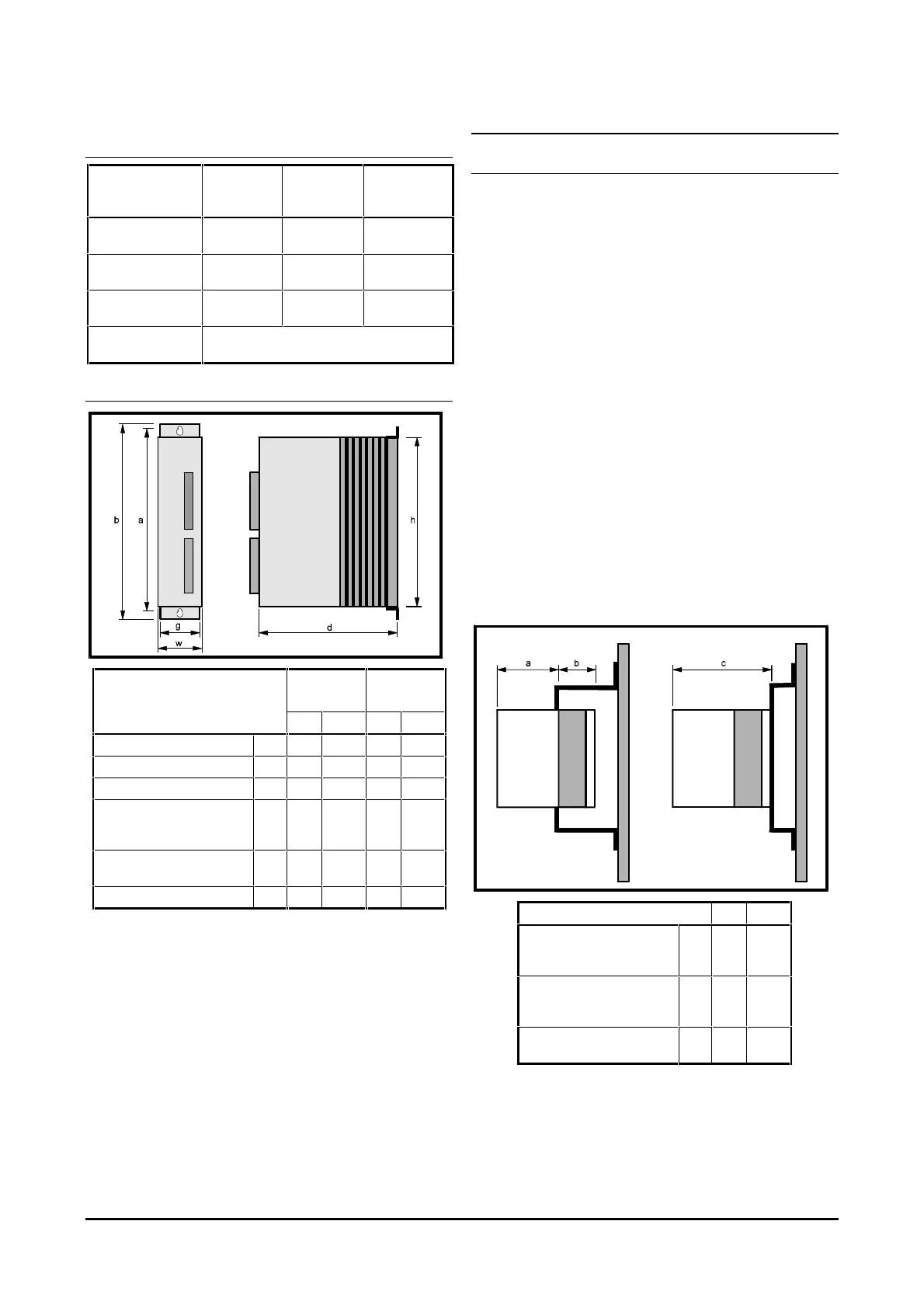
Drive dimensions
Dimensions Midi-
Maestro
Maxi-
Maestro
mm in mm in
Height of case h 196 7
11
/
16
196 7
11
/
16
Width of case w 65 2
9
/
16
84 3
5
/
16
Depth of case d 220 8
5
/
8
220 8
5
/
8
Mounting centres from top
mounting bracket to bottom
mounting bracket
a 215 8
7
/
8
215 8
7
/
8
Height including
mounting brackets
b 235 9
1
/
4
235 9
1
/
4
Width of mounting bracket g 62 2
7
/
16
80 3
1
/
8
Figure 1 Dimensions of the Drive
Mechanical Installation
Mounting location
Mechanical installation has to take into account points
of entry of electrical cables and the fitting of a choke if
required.
The Drive should be located in a place free from dust,
corrosive vapours, gases and all liquids.
Two alternative arrangements for mounting the Drive
are provided. Depending on the position of mounting
brackets, these are:
Surface mounted on a panel or in an enclosure
Through an aperture in a panel so that the
heatsink of the Drive projects from the rear of the
panel. This arrangement can be used for
mounting the Drive through the rear panel of an
enclosure to allow free circulation of air around
the heatsink and to minimize temperature rise
inside the enclosure. This can be beneficial if the
enclosure is to house a number of Drives.
Each mounting bracket is mounted to the heatsink by
two self-tapping screws.
Surface mounting
on a panel
Through-panel
mounting
Frame Frame
Dimensions mm in
Through-panel mounting —
from brackets to front of the
Drive
a 134 5
1
/
4
Through-panel mounting —
from brackets to rear of the
Drive
b843
5
/
16
Surface mounting — from
brackets to front of the Drive
c 222 8
11
/
16
Figure 2 Details of the mounting brackets