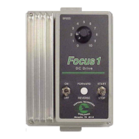
Midi-Maestro and Maxi Maestro Drive
24
Initial start up
1. Disconnect the signal connector from the Drive.
2. When a multi-axis system is to be powered up,
remove the
AC supply fuses for all the Drives
except for the Drive to be tested.
3. Apply power to the connected Drive. After a delay
of about 1 second, the green
LED will light.
4. Check that the motor is free to turn by hand.
5. Check that there is no current flowing through
the motor.
6. Check that the green
LED stays on.
7. Switch off the Drive.
8. Repeat instructions 1 to 7 for all other axes.
Warning
After switching off, wait for about 10 seconds before
re-applying power to the Drives in order to avoid loss
of protection in the Drives already powered.
Warning
The next instruction requires the Drive to be powered
up. Any incorrect wiring to the motor may result in
the motor turning at high speed and in the wrong
direction.
During these operations the load must be disconnected
and the operator must be able to turn the system off
quickly.
1. Check that the speed reference signal is zero
volts.
2. Connect the signal connector to the first Drive.
Switch on the Drive.
3. Check that the motor does not rotate.
4. Enable the Drive.
5. Check that the motor is stationary or turns slowly
due to a signal offset.
6. Apply a signal to the
STOP input.
7. Try to force the motor shaft to turn in both
directions and check torque is applied at zero
speed. This checks that there is symmetric torque
generation.
8. Alter the reference signal for the motor to turn
clockwise or anti-clockwise. Note that the motor
may turn extremely slowly. If the motor rotates
in the reverse direction to the expected one,
reverse the motor and tachogenerator
connections.
9. Repeat operations 1 to 8 for all the other axes.
10. Leave the system powered up for at least
15 minutes in normal working conditions. Check
the I
2
t protection LED is off and the green Drive
normal
LED is on.
If the system does not run as described during
start-up, refer to Fault finding.
Diagnostics
Four LEDs and two digital outputs are available on the
Drive to give the following:
Monitoring the status of the Drive
Diagnostics
I
2
t protection
LED indicators
I
2
t protection indicator
The I
2
t LED is lit when I
2
t exceeds the programmed
value.
When the I
2
t LED is lit, the Drive generates the value
of nominal current set by the
RIN resistor.
I
2
t protection can be caused by:
A heavy working cycle with quick and frequent
accelerations
Reversal of the Drive
Drive rating inadequate.
When I
2
t limiting is not activated, the green LED will
light and a Drive NORMAL output signal will be
produced.
Tachogenerator loss-detection indicator
The TACHO LOSS LED is lit when one of the following
occurs:
• Tachogenerator open or short circuit
• Cable connections short circuit
• Polarity of tachogenerator connections
incorrect
• Tachogenerator not connected
DRIVE NORMAL indicator
The DRIVE NORMAL LED indicates that the Drive is
operating normally. When the
LED is unlit it indicates
at least one of the Drive protection functions is active.

 Loading...


