Midi-Maestro and Maxi Maestro Drive
3
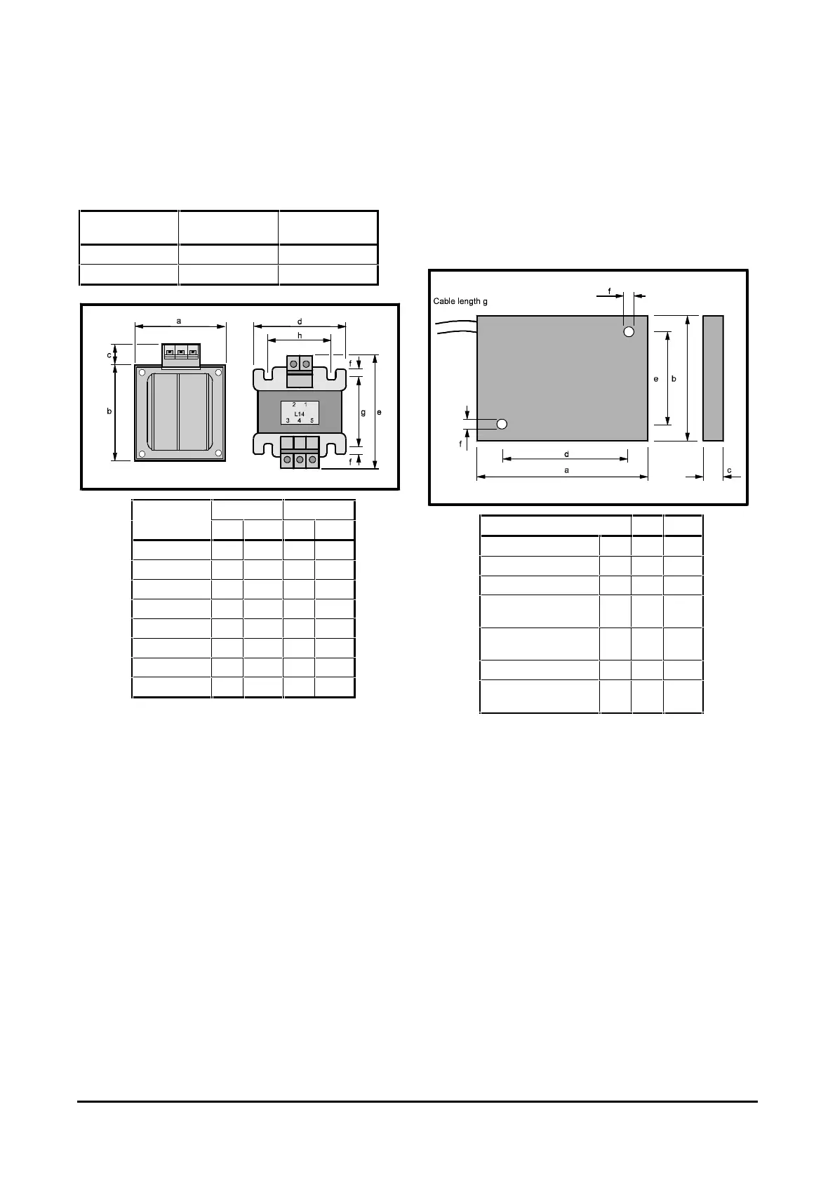
Choke (optional)
When a motor has an inductance value less than the
figure quoted in the following table, a choke is
required. Refer to Figure 3 for dimensions.
Model Minimum
inductance
Required
choke
Midi-Maestro 2 mH L13
Maxi-Maestro 3 mH L14
L13 L14
mm in mm in
84 3
5
/
16
94 3
11
/
16
112 4
3
/
8
100 3
15
/
16
17
5
/
8
15
9
/
16
84 3
5
/
16
94 3
11
/
16
102 4 110 4
5
/
16
8
5
/
16
8
5
/
16
56 2
3
/
16
63 2
1
/
2
57 2
1
/
4
60 2
3
/
8
Figure 3 Dimensions of the
L13 and L14 chokes
Braking resistor
When a Maxi-Maestro Drive is used, or the internal
braking resistor for a Midi-Maestro is insufficient, the
Drive requires an external braking resistor. A braking
resistor is supplied with the Maxi-Maestro Drive.
Refer to Figure 4 for the dimensions of this braking
resistor.
mm in
Length a 107 4
1
/
4
Height b 68 2
11
/
16
Depth c 12
1
/
2
Distance between hole
centres — length
d81 3
3
/
16
Distance between hole
centres — width
e58 2
1
/
4
Hole diameter f 5
3
/
16
Maximum length of
cable
g 300 12
Figure 4 Dimensions of the braking resistor