Midi-Maestro and Maxi Maestro Drive
14
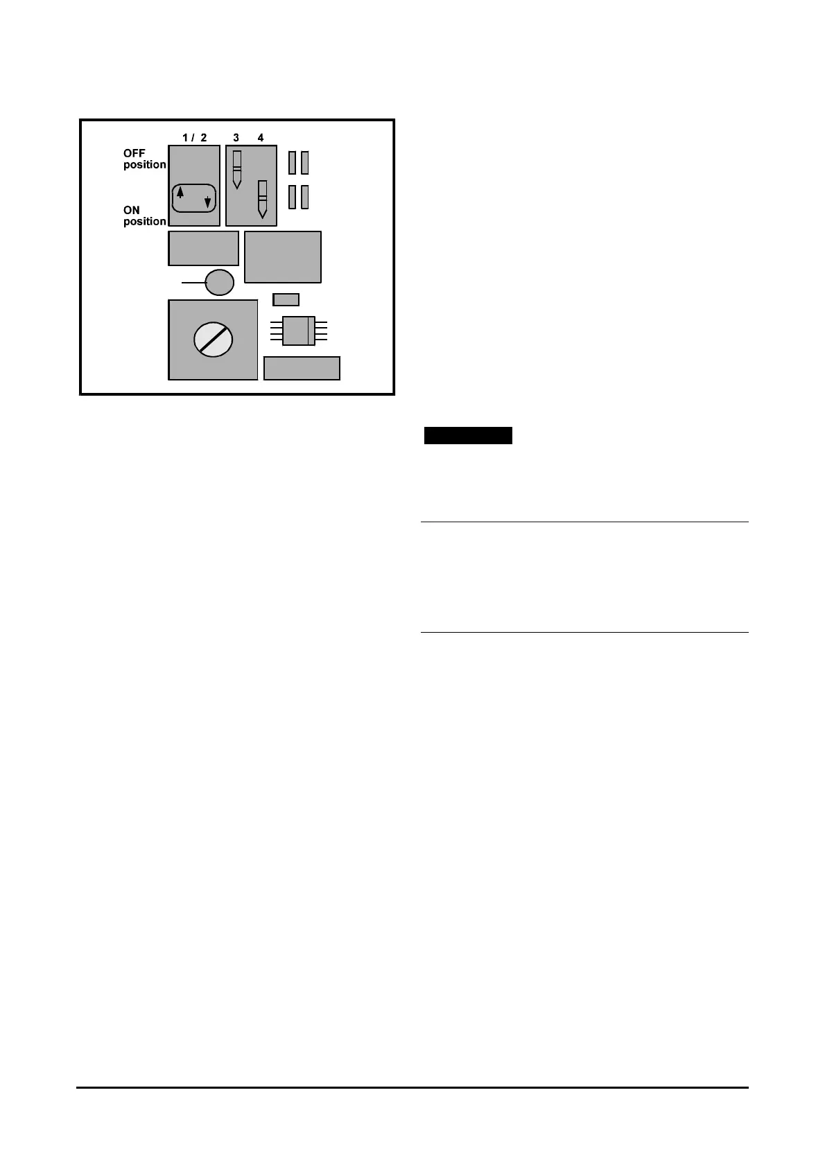
Figure 17 ON and OFF positions of
the switches
Mounted components
The following resistors and capacitors may be required
to be fitted on the daughter board:
RKW resistor
Adjusts the Drive for armature voltage speed
feedback.
RRT resistor
Adjusts the Drive for tachogenerator loss
protection.
RIP resistor
Reduces the peak current to the desired value.
RIN resistor
Reduces the nominal current to the desired value.
RAI resistor
Compensates for the voltage drop due to internal
resistance of the motor.
RS resistor
Adjusts the amount of zero-speed torque applied
to the motor when a
STOP signal is applied to the
Drive.
RT resistor
Normalizes the tachogenerator input signal and
adapts the Drive to the voltage constant of the
tachogenerator.
C1 capacitor
Adjusts integral gain.
C2 capacitor
Adjusts derivative gain.
C3 capacitor
Adjusts the response of the system when the
Drive is in armature feedback mode.
Note
Most applications do not require C1, C2 or C3 to be
used. When an application does require these
capacitors, the recommended value is between 0.1µF
and 5µF.
Making adjustments to the
Midi-Maestro Drive
Zero speed offset
ZERO REF potentiometer
1. Connect the non-inverting input of the speed
reference signal to pin 9 and the inverting input
to pin 10.
2. Set the speed reference signal for zero speed.
3. Remove the connection from pin 15 (
STOP signal).
4. Connect a digital multimeter to pins 11 and 12.
5. Enable the Drive and adjust the
ZERO REF
potentiometer to reduce the multimeter reading to
not more than 1mV.
6. Restore the original wiring.