Midi-Maestro and Maxi Maestro Drive
11
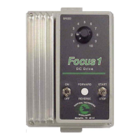
Braking resistor connections
Midi-Maestro
An internal braking resistor is installed in the Drive.
When this is inadequate, a larger resistor may be
connected externally.
The external braking resistor should be connected
between pins 24 and 16 of the power connector.
Ext Drive braking resistor
L3
L2
L1
Earth (Ground)
-DC
CNC
Stop/Start
Emergency
Stop
AC supply
isolator
Braking
resistor
Drive
AC supply
connections
Thermal protection
device
20
21
22
23
24
Power connector
19
20
18
17
16
M2
M1
+DC
Figure 14 Braking resistor connections for the
Midi-Maestro Drive
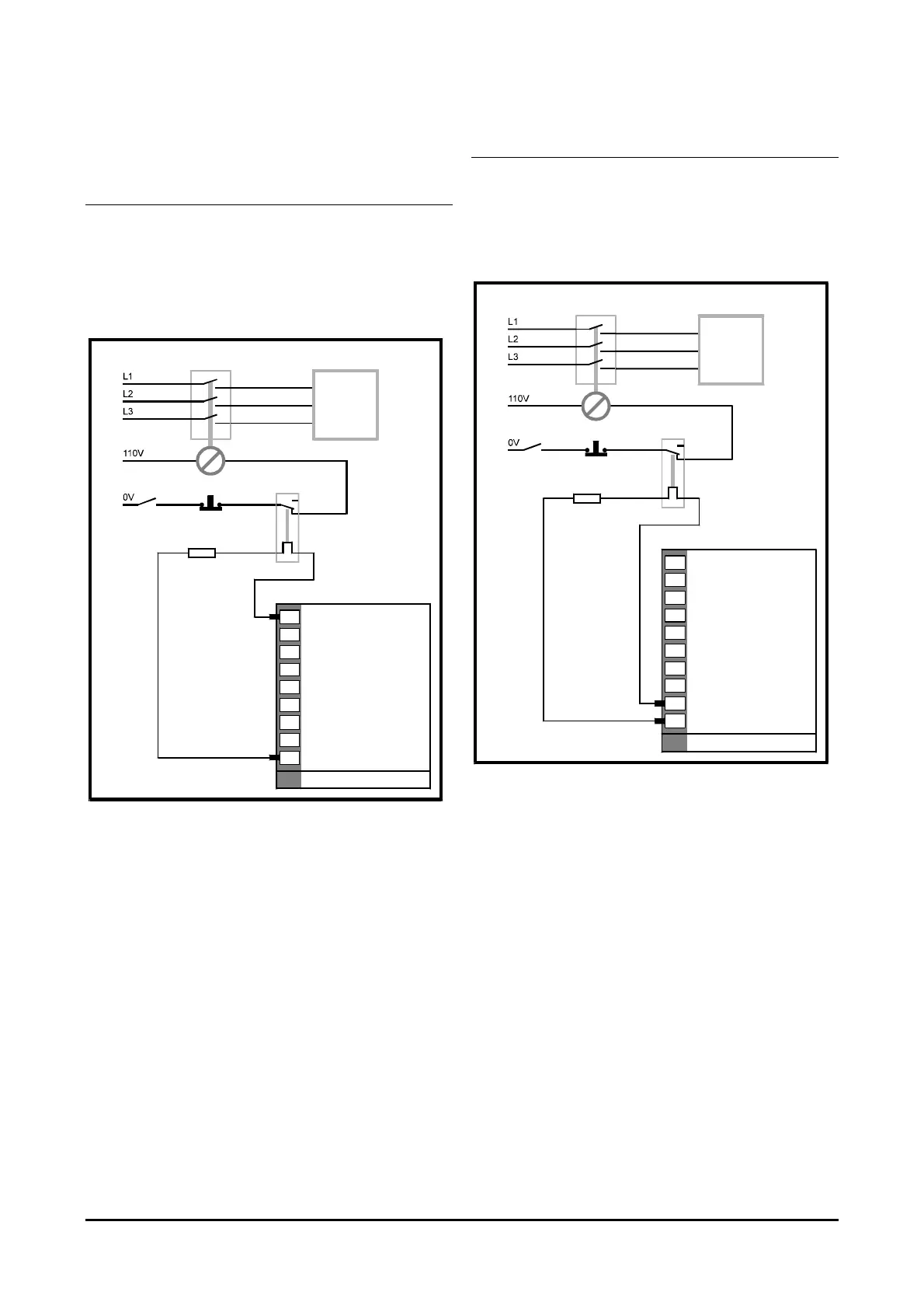
Maxi-Maestro
An external braking resistor is supplied and must be
mounted close to the Drive. When this is inadequate a
larger resistor may be used instead.
The braking resistor should be connected between pins
24 and 25 of the power connector.
Ext Drive braking resistor
Ext Drive braking resistor
L3
L2
L1
Earth (Ground)
-DC
CNC
Stop/Start
Emergency
Stop
AC supply
isolator
Braking
resistor
Drive
AC supply
connections
Thermal protection
device
20
21
22
23
24
25
Power connector
19
20
18
17
16
M2
M1
+DC
Figure 15 Braking resistor connections for the
Maxi-Maestro Drive