Midi-Maestro and Maxi Maestro Drive
12
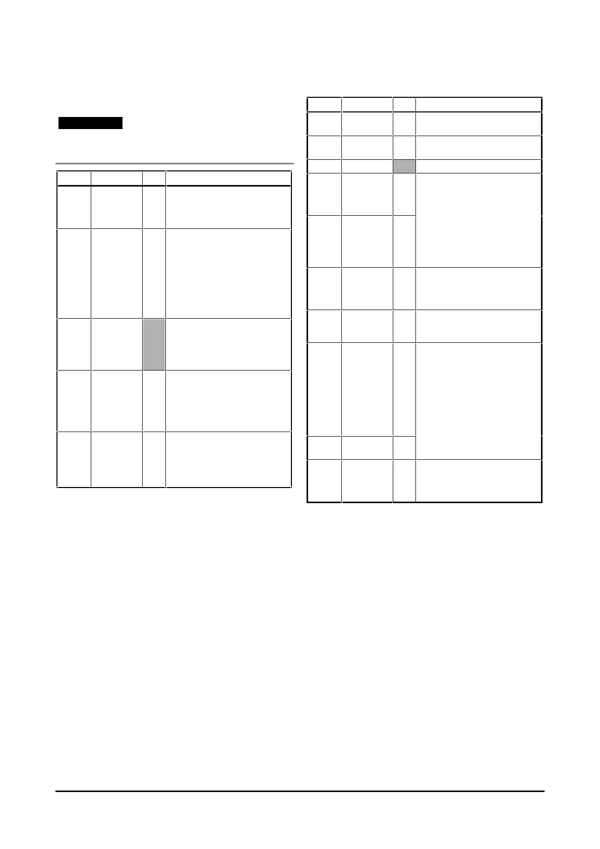
Signal connections
Note
Signal cables and power cables must be segregated
and wired through different trunking.
Pin No. Description I/O Notes
1I
MOT
O Analog signal proportional to the
effective current in the motor.
Output signal ± 8V at maximum
current.
2 TPRC I/O Analog signal proportional to the
value of the requested current.
Signal range ±10V. When at ±10V
the Drive generates peak current.
When used as an input, and the
same voltage range is applied, the
Drive becomes a current amplifier
using the applied voltage as
current reference.
30V Internally connected to:
Pin 8 (0V)
Pin 12 (Tacho)
Ground
Pin 19 (–DC)
4I
2
t O A signal is produced from this
output during I
2
t current limiting
and the LED I
2
t is lit. Maximum
voltage available is 47V. Drive
capability when no signal is given
is 100mA.
5 ENABLE I When a 10V DC to 30V DC signal
is applied to this pin, the Drive is
enabled.
When the signal is discontinued,
the Drive is disabled (0V).
Pin No. Description I/O
6 +10V
reference
O
7 –10V
reference
O
80V
9 SPEED
REF.
(inverting
input)
I
The speed reference signal input
is a differential input to minimize
10 SPEED
REF.
(non-
inverting
input)
I
When a differential signal from the
external controller is not available,
11 TACHO
(non-
inverting
input)
I
12 TACHO
(inverting
input)
I
13 DRIVE
STATUS
O
Pins 13 and 14 internally
connected through a contact when
the green LED is lit and the Drive
When a protection functions is
active, the contact is open. The
outputs are volt free. The contact
14 DRIVE
STATUS
O
15 STOP I
applied, the STOP function is
enabled. This is a controlled
STOP giving torque at zero speed.