Midi-Maestro and Maxi Maestro Drive
5
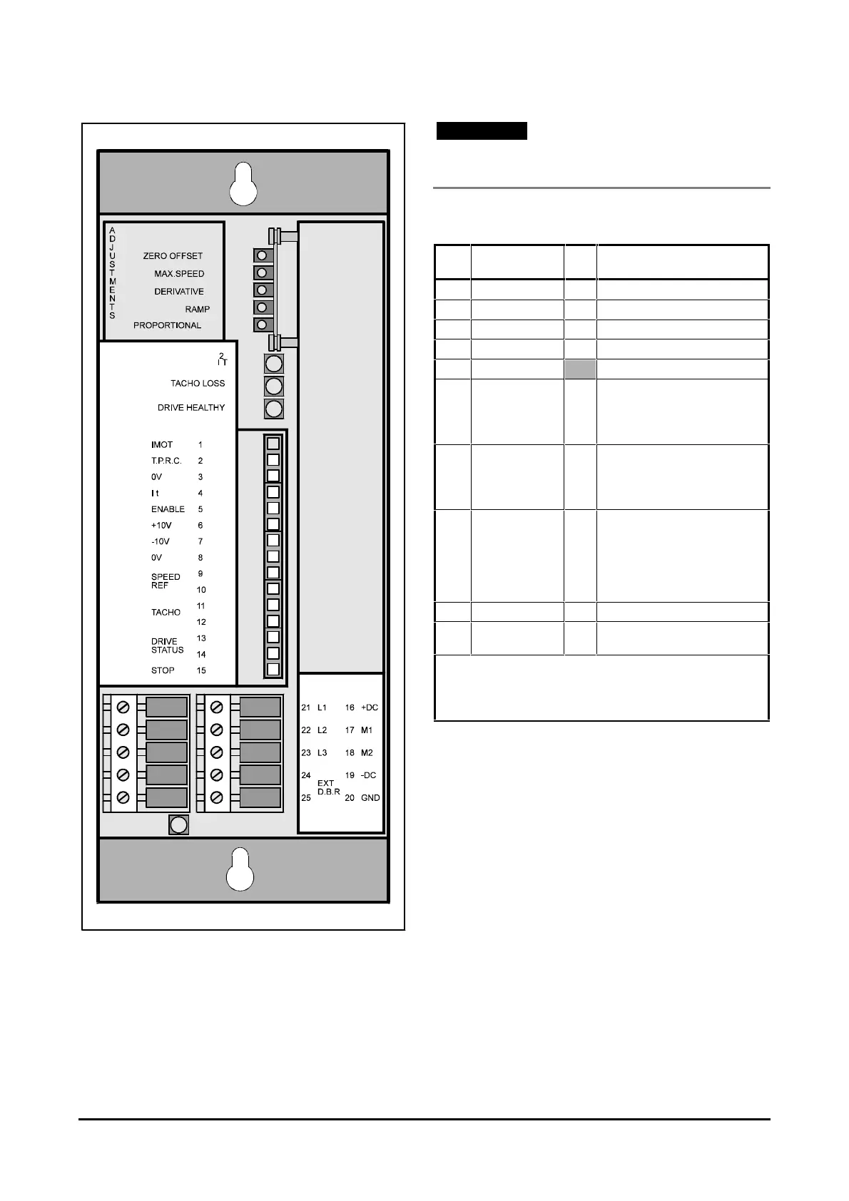
Figure 6 Locations of the signal and power
connections in the Maxi-Maestro
Drive
Note
Signal cables and power cables must be segregated
and wired through different trunking.
Power connector
Pin
No.
Description I/O Notes
16 +DC O +DC bus.
17 MOT1 O + terminal for motor.
18 MOT2 O – terminal for motor.
19 –DC O –DC bus.
20 E Ground.
21 L1 I Phase 1 from three-phase
transformer.
Line 1 from single-phase
transformer.
22 L2 I Phase 2 from three-phase
transformer.
Line 2 from single-phase
transformer.
23 L3 I Phase 3 from three-phase
transformer.
Note — Transformer secondary
wiring must be delta connected.
The phase sequence has no
effect.
24 EXT DBR O External braking resistor.
25 EXT DBR O (Maxi-Maestro only)
External braking resistor.
An additional braking resistor for the Midi-Maestro Drive is
connected between pins 24 and 16.
The braking resistor for the Maxi-Maestro is connected between
pins 24 and 25.