Midi-Maestro and Maxi Maestro Drive
7
DC bus voltage
DC bus voltage without load, V DC = Vs ×× 1.41
where Vs = transformer secondary voltage (off-load)
The following table shows
DC bus voltage and
transformer secondary voltage.
Voltage
Midi-Maestro
140 ×× 8/16
Midi-Maestro
140 ×× 14/28
Maxi-Maestro
200 ×× 25/50
DC bus 150 V 150 V 212 V
Transformer
secondary
105 V 105 V 150 V
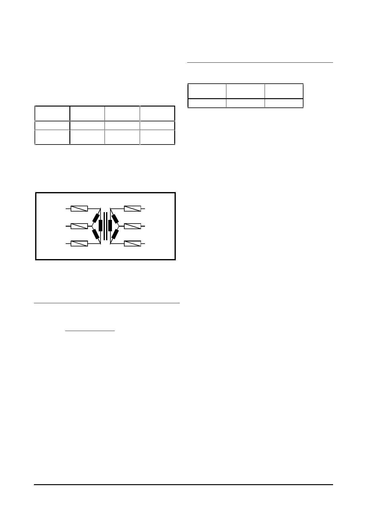
Supply fuses
A fuse should be fitted in each of the transformer
primary and secondary circuits.
AC supply Supply to the Drive
Primary Secondary
Figure 9 Fuses in the transformer primary
and secondary circuits
Primary-circuit fuses
Use the following equation to calculate the rating of
the fuses in the primary circuit:
Amps =
Transformer VA rating
RMS primary voltage
Secondary-circuit fuses
Refer to the following table for the rating of the fuses
in the secondary circuit.
Midi-Maestro
140 ×× 14/28
Maxi-Maestro
200 ×× 25/50
16 A 30 A
If more than one Drive is connected to a secondary
winding, it is necessary to install three fuses for each
Drive.
Ground connections
To avoid unnecessary tripping of the Drive, one
common ground point must be used to connect the
signal common and the power common. The shortest
possible wiring should be used. Refer to Figure 12.
A grounding bar mounted on insulated supports and
having the dimensions given in Figure 12 may be used.
No significant voltage drop should occur between
connections.
The ground connections shown in Figure 12 should
assist in minimising the effects of signal noise.
The connection to the chassis terminal of the enclosure
must be adequately sized.
If in doubt, consult the supplier of the Drive.