Midi-Maestro and Maxi Maestro Drive
13
Setting up the Drive
Potentiometers, mounted components and switches
fitted on a daughter board are used to configure the
Drive. If there is a need to replace the Drive, and the
configuration is required in the replacement, the
daughter board can be removed and installed in the
replacement Drive.
Note
An RT resistor is fitted as standard. The value is
5.1kΩ for tachogenerator voltage constant, Ke = 10
and maximum motor speed = 3000
RPM.
Switch 1/2 and 4 are set at
ON
Switch 3 is set at OFF.
Note
The daughter board fitted to the Drive may be
different in layout to the one described. If this is the
case, refer to Alternative Daughter Boards.
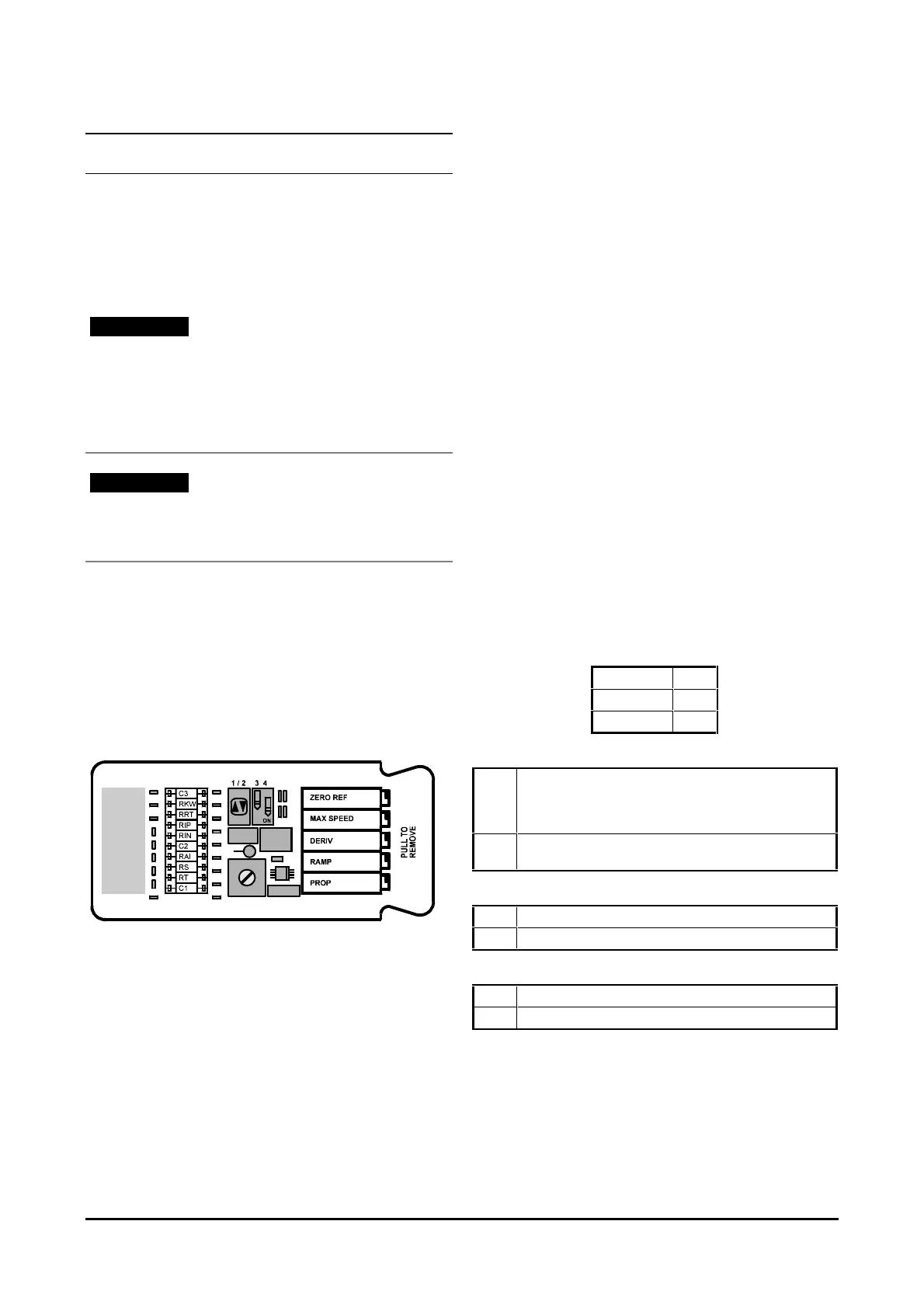
Potentiometers
Five potentiometers are labelled as follows:
ZERO REF
MAX SPEED
DERIVATIVE
RAMP
PROPORTIONAL GAIN
Figure 16 Daughter board
ZERO REF potentiometer
Adjust this potentiometer to cancel any offset in the
external speed reference signal.
MAX SPEED potentiometer
Turn the potentiometer anti-clockwise to reduce the
maximum motor speed to 50%. Turn the
potentiometer clockwise to increase the maximum
motor speed to 120%.
DERIVATIVE Potentiometer
Turn the potentiometer clockwise to reduce the
amount of overshoot in the system response by
increasing the derivative gain of the
PID amplifier.
RAMP potentiometer
Adjust the potentiometer to increase or decrease the
time the motor reaches maximum speed from 0 second
to 2 seconds
PROPORTIONAL potentiometer
Turn the potentiometer clockwise to increase the
proportional gain of the
PID amplifier.
Switches
The standard settings for the switches are as follows:
ON
OFF
ON
Switch 1 / 2
ON Enables speed control with tachogenerator feedback and
disables the armature feedback function. When used in
this position, remove
RAI resistor.
OFF Disables speed control with tachogenerator feedback and
enables the armature feedback function.
Switch 3
ON Enables tacho loss protection.
OFF Disables tacho loss protection.
Switch 4
ON Disables acceleration and deceleration ramp.
OFF Enables acceleration and deceleration ramp.