Midi-Maestro and Maxi Maestro Drive
21
Adjusting speed for operation in
armature feedback mode
RKW resistor
Armature feedback mode can be used when a
tachogenerator is not fitted to the motor. Speed
control is then less precise. Speed is controlled by
using the motor voltage as feedback.
Voltage drop due to motor resistance can be
compensated by adjusting the value of the
RAI resistor.
1. Set Switch 1/2 at
OFF to enable operation with
armature feedback.
2. Set Switch 3 at
OFF to disable tachogenerator loss
protection.
3. Use the following equation to calculate the correct
value of
RKW resistor:
RKW Vm Ke==××××77 7.
Where:
Vm = Maximum speed in
RPM ÷1000
Ke = Motor voltage constant (voltage at 1000
RPM
— in general V × 1000÷RPM)
4. Calculating the value of the
RAI resistor can be
difficult since it is a function of the following:
• Motor characteristics. (eg. armature resistance
and temperature).
• Brush resistance (changing with wear)
An approximate value may be found
experimentally using a
RAI resistor value of
400kΩ to 600kΩ.
Caution
Too low a value for the RAI resistor may modify the
velocity loop response. For guidance, contact Control
Techniques.
Adjusting the peak current
RIP resistor
When a
RIN resistor is fitted, I
PEAK
may become
excessively high in relation to I
NOM
. To reduce the
value of the peak current, use a
RIP resistor.
Note
The new value for I
PEAK
must be ignored when the
value of
RIN is calculated.
Use the following equation to calculate the value of the
RIP resistor:
(())
(())
RIP =
10 I
I-I
k
LIM
PEAK LIM
××
ΩΩ
Where:
I
LIM
= the new value required for I
PEAK
Note
When the peak current is reduced, the ratio between
I
PEAK
and I
NOM
is altered. This alteration increases the
time before I
2
t protection takes place.
In this case, the peak current is supplied for more
than 2 seconds.
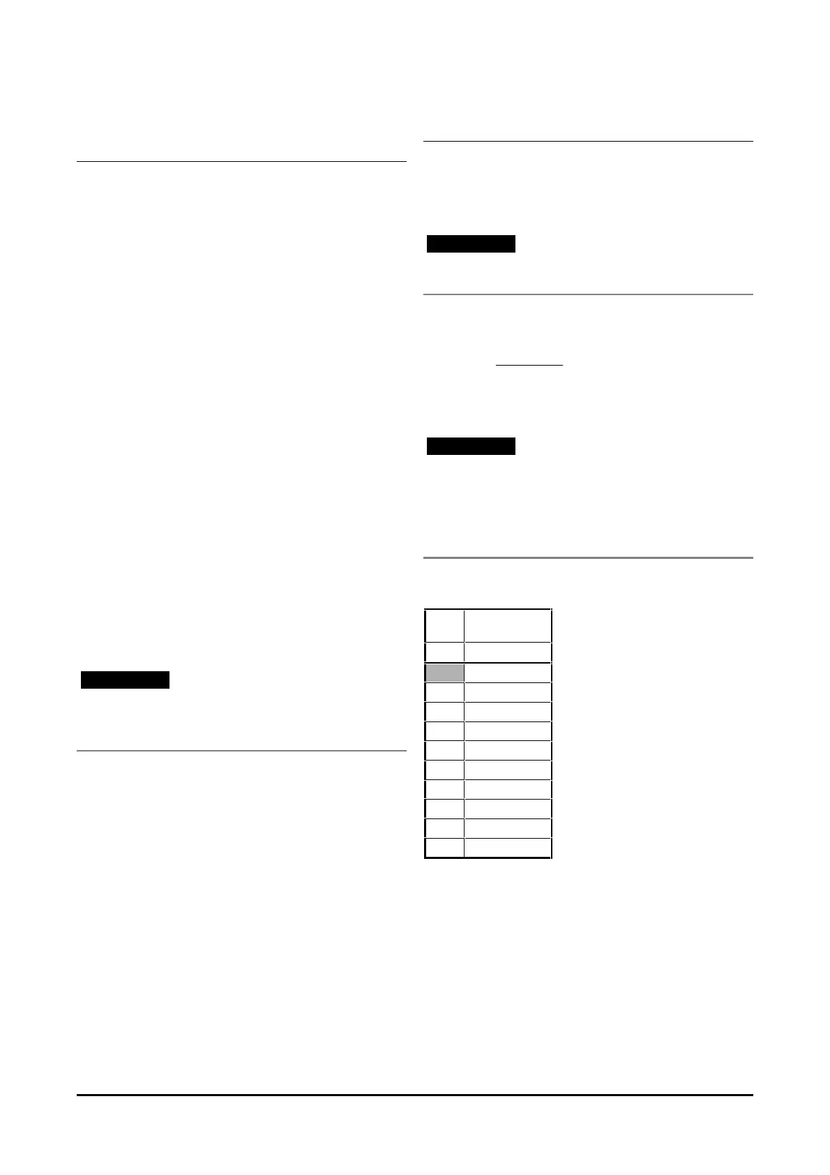
The following table may be used for finding an
approximate value of I
PEAK
.
RIP Maxi-Maestro
200 ×× 25/50
kΩΩ
I
PEAK
50
220.0 48
120.0 46
75.0 44
56.0 42
39.0 40
32.0 38
27.0 36
22.0 34
18.0 32