2 Configuration and Functions
2.1 The Combi Oven's Configuration and Functions
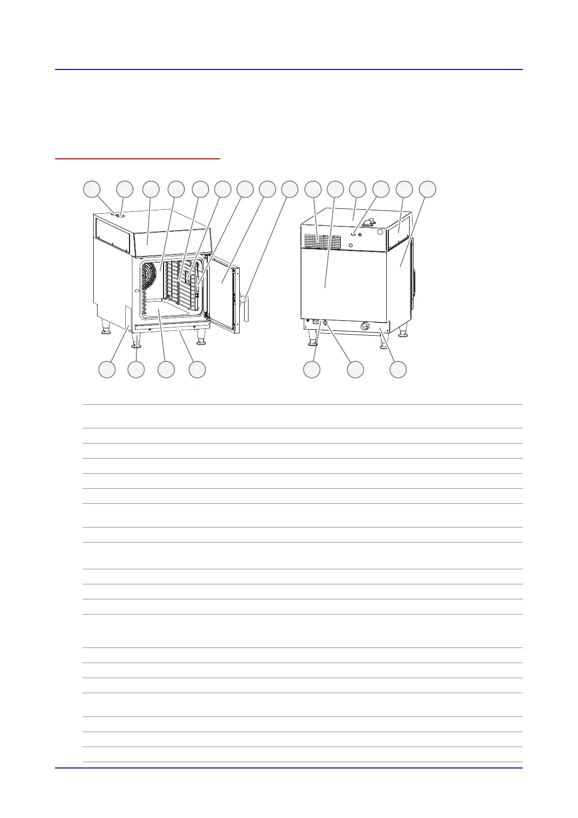
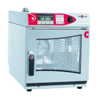
Parts and functions
The figure below shows a size 6.10 mini combi oven used as an example representing all models:
1 32 4 5 6 8 9 1110 12
19 1822 21 20 1617
1513 147
No. Designation Function
1
Ventilation port Draws in ambient air in order to remove moisture from the oven
cavity
2
Air vent Lets hot steam escape
3
Control panel Used to operate the unit
4
Suction panel Used to distribute heat uniformly within the oven cavity
5
Rack Used to hold standard-size bakeware
6
Oven light Illuminates the oven cavity
7
Core temperature probe
(optional)
Used to measure the food's core temperature
8
Unit door Seals the oven cavity
9
Door handle
■
Used to open and close the unit door
■
Cracked-open position for safely opening the unit ("safety lock")
10
Vents Used for ventilation purposes
11
Rear panel Covers the unit's wiring compartment
12
Top enclosure Covers the unit's control electronics
13
Condensation hood con‐
nection (optional with
easyTouch)
Used to connect a Halton condensation hood
14
Cover on top enclosure Used to access the electronics in the top enclosure
15
Outer case Used to cover the inside of the unit
16
Connection angle bracket Used to cover the connection area
17
Condensation hood con‐
nection (optional)
Used to connect a mini Condensation Hood Pro
18
Network connection Used to connect to a network
19
Openings in base Used for ventilation purposes
20
Oven cavity Is where food is placed while it is being cooked
2 Configuration and Functions
Installation Manual 11