Do you have a question about the Corghi ProLine 60 and is the answer not in the manual?
Provides safe and practical instructions for the use and maintenance of the wheel balancer.
Details care during unpacking, assembly, lifting, and setting up the machine safely.
Outlines essential conditions for safe machine operation and operator responsibilities.
Explains symbols like lightning, rotating parts, and grounding for user safety.
Illustrates the placement of safety and information decals on the machine.
Provides details on machine identification and technical data found on the serial number plate.
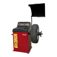
Refers to instructions for installing the protective hood, shown on page 29.
Guides on cleaning and connecting the shaft using a spanner and screw.
Specifies grounding requirements for the power cable and safe electrical installation by qualified staff.
Highlights key features like high intelligence computer, precision bearing shaft, and automatic balance checks.
Lists technical data including voltage, power, speed, accuracy, noise, and dimensions.
Explains how the balancing sensor, microprocessor, and main shaft work together to calculate unbalance.
Instructions for placing, carrying, and storing the machine according to package labels and environmental conditions.
Procedures for removing the connect bolt, placing the machine on a flat floor, and storing it indoors.
Steps for securing the machine to the floor using anchor bolts and washers.
Specifies that balancers are for wheel unbalances and must use protective guards.
Illustrates operator positions for different work phases like mounting and program selection.
Basic setup of the machine's components and controls, including the control panel.
Identifies keys, buttons, and display elements for machine operation and parameter input.
Steps for preparing the tire and wheel before starting the balancing process.
Describes positive, negative, and flange disk methods for mounting different tire sizes.
Guides on entering distance (DIS), rim breadth (Br), and diameter (Dia) values for the wheel.
Explains how to convert units for rim breadth and diameter between inches and millimeters.
Details residual unbalance display, balance mode selection (Dynamic, Static, ALU), and their applications.
Offers additional advice on achieving accurate balance effects with aluminum alloy rims.
Introduces functions for protective cover, beeper setup, and sensor testing.
Lists common error codes and their solutions.
Provides instructions for replacing the press sensor, including part disassembly and reassembly.
Offers solutions for common issues like the machine not displaying, not braking, or inaccurate balance.
Lists included accessories such as cones, pliers, quick nut, bowl, and hood with quantities.
Advises on periodic lubrication of the motor and balance shaft bearings and grease types.
Covers proper disposal of electrical equipment, environmental information, and firefighting means.
Step-by-step guide for balancing a tire, including parameter input and weight application.
Details how to set up protective hood, beeper, and APP (unbalance setup) functions.
Instructions for performing self-calibration when the machine is unused or balance is inaccurate.
| Brand | Corghi |
|---|---|
| Model | ProLine 60 |
| Category | Wheel Balancers |
| Language | English |