42 ProLine 60 - Operator's Manual
6. CONFIGURATION & USE
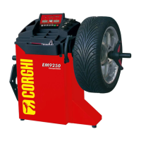
6.1 CONFIGURATION
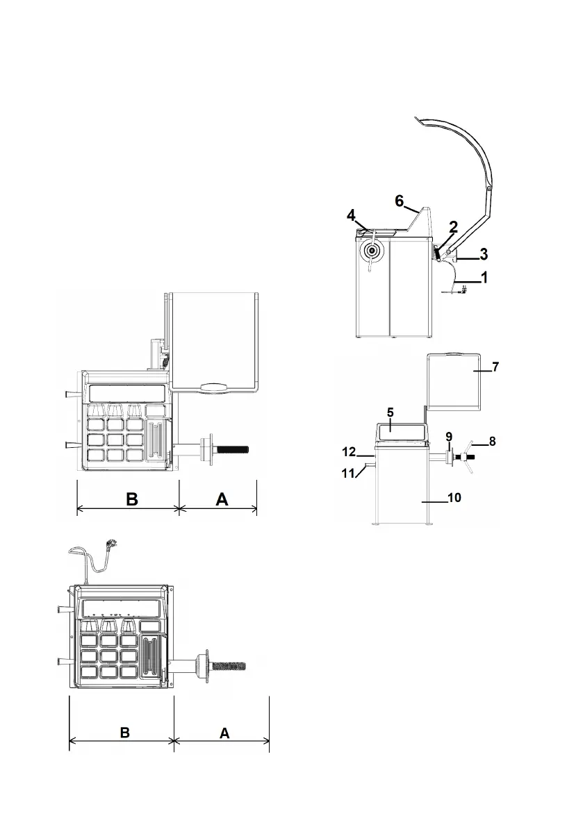
1 - power &plug 2 - Return Spring
3 - main switch 4 -
Manual distance detector
5 - control panel 6 - Weight Tray
7 - Hood 8 - Quick Nut
9 - Balance Shaft 10 - body
11 -
Cone Storage Handle
12 - power switch
5.1.8 OPERATOR POSITION
Figure 11 shows the operator's positions during
the various work phases:
A Mounting/Demounting, spin, dimension de-
tection (where foreseen) and wheel balancing
operations
B Machine program selection
In this way, the operator is able to perform,
monitor and check the outcome of each wheel
balancing and intervene in case of unforeseen
events.