1.1 The Outlet Piping Should
Include the Following
1. A liquid lled pressure gauge should be installed in the
pump outlet or near it. A pressure gauge is necessary
to determine the efficiency of your pumping system.
2. A hydrostatic relief valve is required by most state laws
and for your own safety.
3. If a meter with a vapor eliminator is installed, pipe the
eliminator outlet to the top of your tank. Never pipe the
eliminator into the pump inlet piping or into the liquid
part of the system at any point.
4. The meter back-pressure valve may be piped into the
tank top or into the pump inlet piping.
5. The discharge piping should be at least the same size
as the meter.
1.2 The Bypass System
The internal safety relief valve is intended as a safety
device and not as an operational bypass valve. The
external bypass valve should be set at a differential
pressure lower than the internal relief valve and may be
connected to the tank at any convenient point, liquid or
vapor. All Z-Series pumps (except ZX2000, which is set
at 175 psid) are set near 150 psid.
ZH2000 Foot mounted hydraulic drive with NPT
connections
ZX2000 Foot mounted with NPT connections and high
pressure internal relief valve spring (175 psid
rather than the standard 150 psid)
ZHX2000 Foot mounted hydraulic drive with NPT
connections and high pressure internal relief
valve spring (175 psid rather than the standard
150 psid)
1.3 Power Take-off (PTO)
Drive Systems
Proper pump operation and long life are directly dependent
upon a good drive system. Many truck pumps utilize a
power train consisting of shafts and universal joints from
a power take-off shaft on the truck engine to the pump.
There are several basic principles that should be followed
in laying out a PTO drive. These principles should not be
violated. Following them will produce a workable power train
that results in long pump life and reduced drive wear.
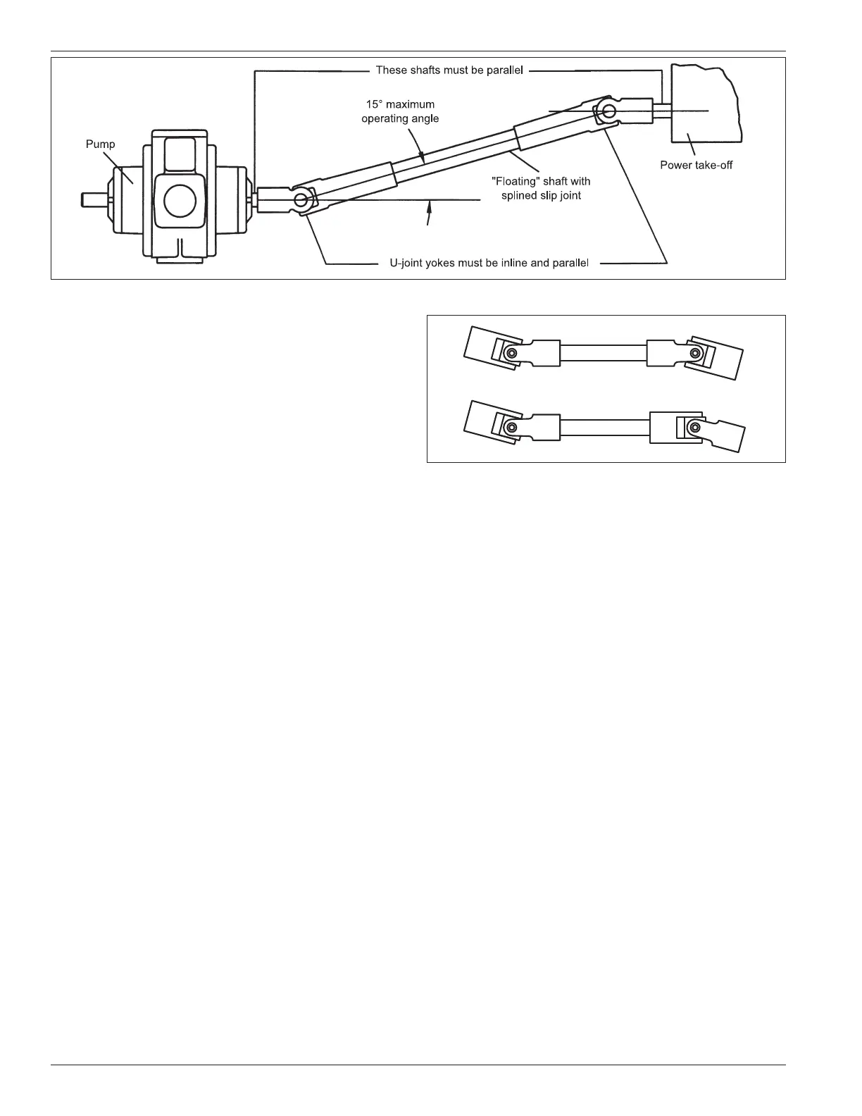
First, the driver shaft and the driven shaft must be parallel
to one another within plus or minus one degree. Improper
alignment will cause jerking and back and forth “whip” to the
pump shaft, thereby imparting a surging pulsation to the liquid
ow, which results in noise, vibration, and abnormal wear.
Second, the angle of the “oating” shaft should be within
the limits for the particular equipment being used (usually
a maximum of 15° at pump speeds up to 800 RPM). To
ensure that shaft expansion or contraction does not distort
the drive system, a splined slip joint should be placed
between the two universal joints. The drive shaft should
be of the “splined” or slip type to permit the shaft to adjust
for PTO movement and twisting of the truck frame. A xed
drive shaft transmits the forces directly to the pump and
PTO which will shorten the life of both considerably.
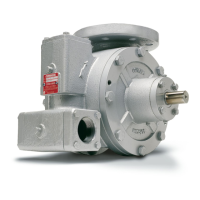
Third, the yokes of the drive shaft universal joints must be
in a parallel position. Figures one and two illustrate the
proper arrangement.
Figure 1.1: Shaft Alignment
Correct assembly
Incorrect assembly
Figure 1.2: Universal Joint Alignment
6