You can detect this “pull down” in pressure by observing your
truck tank pressure gauge as the pump is operating.
To prevent this violent liquid boiling, pressure in some form
must be introduced into the truck tank. The simple way to
accomplish this is to “equalize” between the truck tank and
the receiving tank. Equalizing takes the higher pressure
vapors from the receiving tank and returns them to the truck
tank. As a result, the void left by the receding liquid is lled.
This in turn lessens the need for the liquid to boil excessively.
The equalizing principle is necessary for volatile liquids.
NOTE: EQUALIZING BETWEEN TANKS OR THE
ADDITION OF PRESSURE IS NOT A LEGAL
TRANSFER IN MOST STATES. IF EQUALIZING LINES
ARE NOT PERMITTED REMEMBER THAT A QUIET PUMP IS
AN EFFICIENT PUMP. A NOISY PUMP IS NOT EFFICIENT
AND THE CONDITIONS THAT CAUSE THE NOISE ALSO
CAUSE WEAR TO INTERNAL PARTS. OPERATE THE PUMP
AT SPEEDS THAT RESULT IN A “QUIET” TRANSFER.
NOTE: EVEN WITH THIS INTERNAL SAFETY VALVE,
AN EXTERNAL BYPASS VALVE MUST BE INSTALLED.
Chapter 3—Installation of the
Z-Series Coro-Vane
®
Stationary Pump
NOTE: All pumps should be installed in a well ventilated area.
The installation of the Coro-Vane
®
pump is simple. However,
in order for the pump to deliver optimum performance, the
principles discussed in this book should be followed. The
piping details are furnished to illustrate methods proved
by hundreds of installations. Your own needs may require
slight variations, but every effort should be made to follow
the recommendations identied in this manual.
No pump can discharge more liquid than it receives, so
the pump location and the inlet piping must be given
careful attention. If the inlet piping is inadequate to supply
the demand of the pump, you may expect trouble.
For the transfer of ammable liquids like LPG, the pump
must be installed according to the applicable local safety
and health regulations. The installer and/or the user must
take into account the following:
• The pump must be located as near the storage tank as
possible. For best results the pump inlet line including
the vertical line from the tank should not exceed 12 feet
(3.7 m) in length.
• The bottom of the tank should be at least two feet (0.6
m) above the pump center line. For best results four feet
(1.2 m) is preferred.
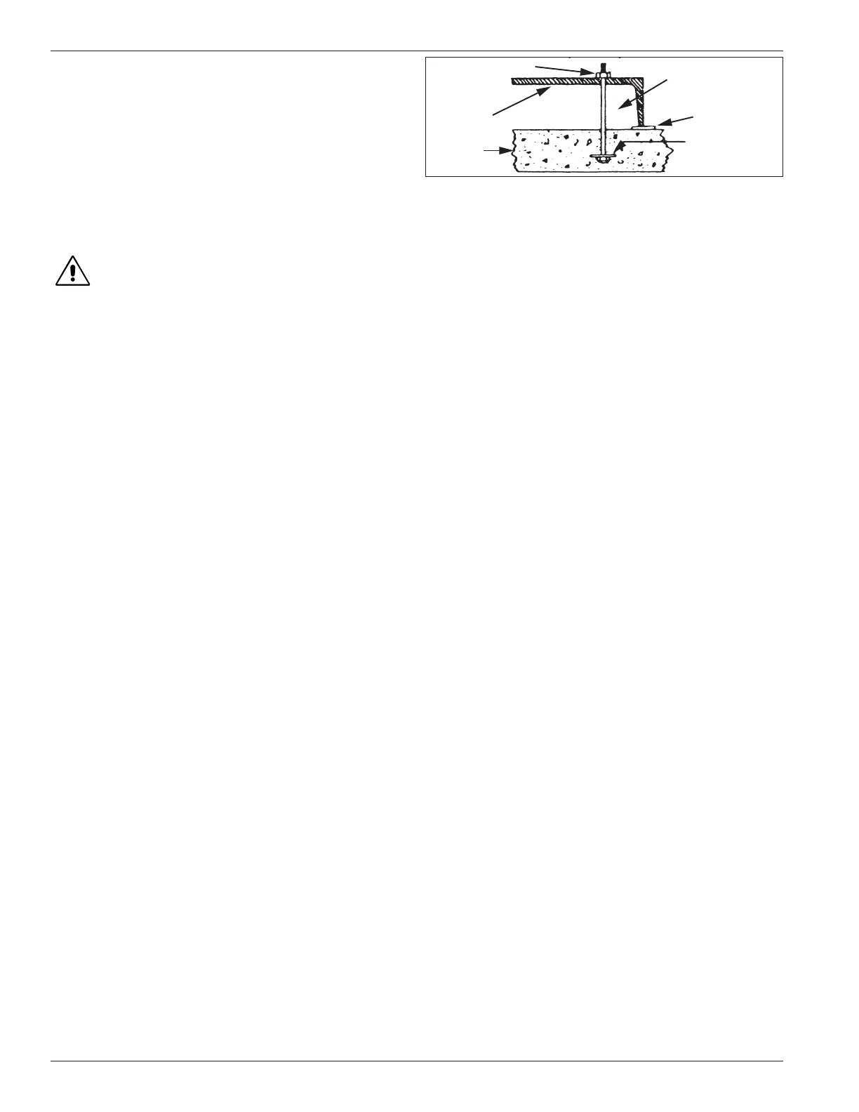
• The foundation for the pump is important. The foundation
must be rm, level and preferably made of concrete. The
suggestions in gure three should be observed.
• Potential risk due to local conditions regarding the
installation and operation (e.g. poor ventilation and
additional risks due to other elements in the vicinity, etc.).
• Qualication of the personnel.
• Type of liquid being transferred.
• Specic safety measures to be applied (e.g. gas
detection, automatic shut-off valves, personal protective
equipment, etc.).
Appendix A shows the weight of the bare pump for each
model. For handling a bare pump, lifting slings should be
used. Web slings are preferred over metal slings to minimize
damage to the paint. See Appendix D for outline dimensions.
3.1 The Inlet Piping Should Include
the Following
1. The tank excess ow valve (EFV) should have a ow
rate of 1-1/2 to 2 times the capacity of he pump. Do not
use an EFV without knowing its ow capacity.
2. The tank shut-off valve should be a free-ow type and
not a standard globe valve.
3. A strainer of the “Y” type, with 30 to 40 mesh screen,
must be on the inlet line of the pump. (Mesh size
indicates the number of openings per lineal inch). A
10x pipe diameter before the pump is recommended.
4. Use a exible connection in the pump inlet and outlet
piping to compensate for piping strains.
5. Use an eccentric swage at the pump inlet nozzle to
change the line size (at side up).
6. Make the inlet line level or slope it downward to the pump.
3.2 The Outlet Piping Should
Include the Following
1. A liquid lled pressure gauge should be installed in the
pump outlet or near it. A pressure gauge is necessary
to determine the efficiency of your pumping system.
2. A hydrostatic relief valve is required by most state laws
and for your own safety.
Figure 3.1
Concrete
Large washer
Metal shim
NOTE: Z4500
baseplate should be
filled with grout.
Pump base
1/2" x 8" anchor bolt
8