1018029-E_03/22Page 15
AUXILIARY LIMIT SWITCH
If outages persist, call a qualied service technician.
MAINTENANCE INSTRUCTIONS
1.
technician. The appliance should be inspected before use
and at least annually by a professional service technician.
More frequent cleaning may be required due to excessive
lint from carpeting, bedding material, etc. It is imperative that
control compartments, burners, pilot burners, circulating air
clean.
2. The bearings of the motor should be oiled every six months
3. The appliance area must be kept clear and free of any
and liquids.
not be obstructed.
5. Periodic examination of the entire vent-ilation system as a
routine part of the safety performance check is recommended
on an annual basis.
IMPORTANT: Keep burner and control compartment
clean. Vacuum burner compartment at the start of the
heating season or as often as needed.
NOTE: It is advised that the burner ames be checked
at least twice during the heating season for any
changes in burner ame characteristics.
115 VAC 60 HZ – Less than 12 Amps:
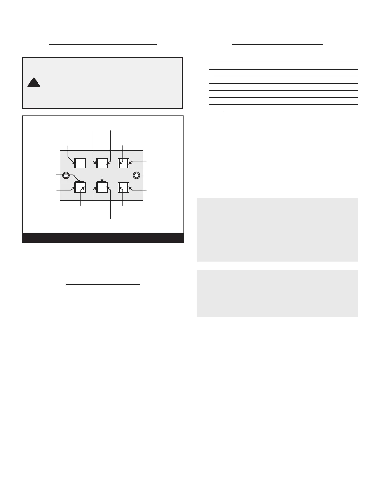
TERMINAL BLOCK WIRING DIAGRAM
CF403, 404, 407, 408, 553, 554, 557 & 558
(
D-H
)
91123
Motor (White)
Motor (Green) Motor (Black)
Transformer (Black)
Transformer (Black)
Limit
(Blue)
Terminal
Board
Ground
(Green)
Cord
(Green)
Selector
(Black)
CAUTION:
Label all wires prior to disconnection when
servicing controls. Wiring errors can cause
improper & dangerous operation. Verify
proper operation after servicing.
!


 To Next Page