1018029-E_03/22Page 9
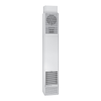
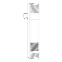
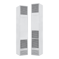
Gas Inlet Hole
Diameter
Knockout
FIG. 8
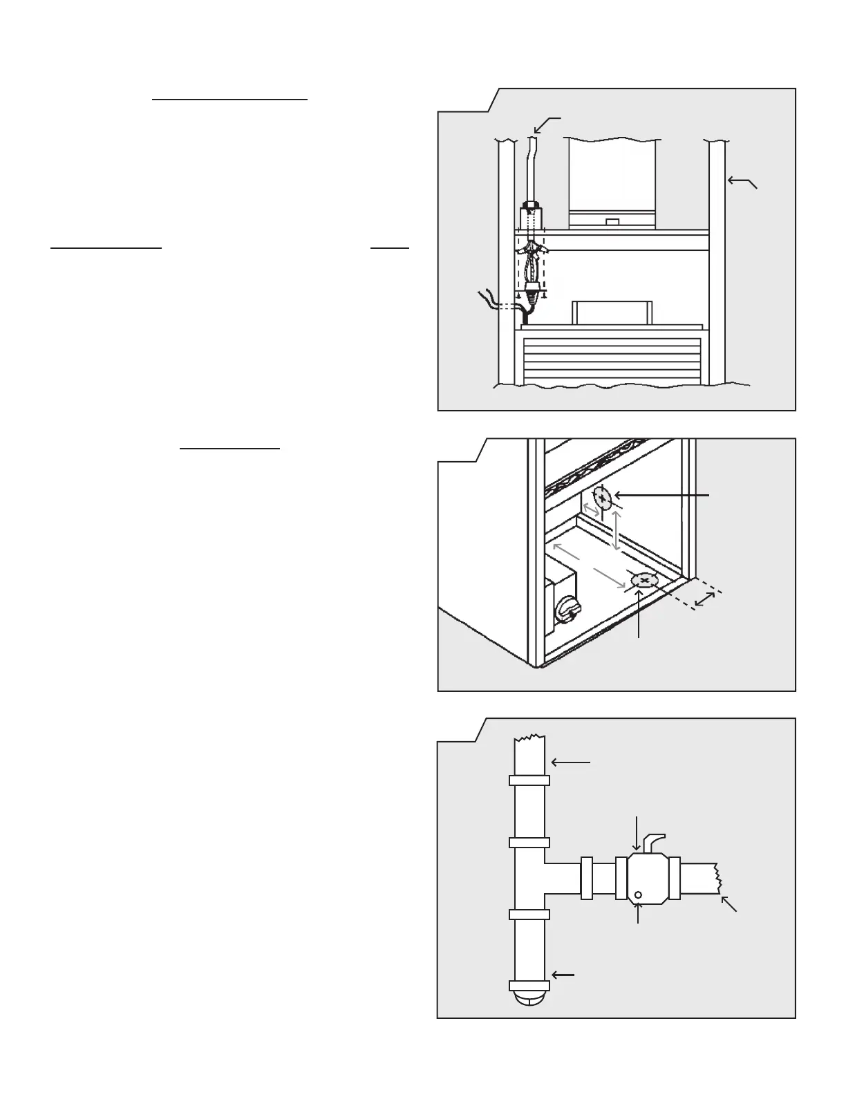
GAS ROUGH-IN
ELECTRICAL ROUGH-IN
Check local codes for requirements as to the size and type
of gas line required. See Figure 8 for location of gas inlet
holes in furnace cabinet.
accessible for test gauge connection should be installed
immediately upstream of the gas supply connection to
the appliance. Some codes and ordinances require that
the manual valve be located outside the appliance. See
Figure 9.
disconnected from the gas supply piping system during any
pressure testing of that system at test pressures in excess
of ½ psig.
The appliance must be isolated from the gas supply piping
any pressure testing of the gas supply piping system at test
pressures equal to or less than ½ pig.
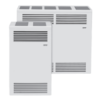
It is required by the National Fuel Gas Code that a drip
line be installed near the gas inlet. This should consist of a
vertical length of pipe tee connected into the gas line that
particles may collect.
FIG. 7
Wire Nut (not provided)
Header Plate
115 V.A.C. Line In
B-W
Vent Pipe
2x4
Stud
To Heater Gas
Control Valve
Drip Leg
Pressure Tap
Gas
Supply
Line
FIG. 9
located on top of header plate for recessed, or in a receptacle
Consult local codes or ordinances. See Figure 7.
MODEL NUMBER AMPS
CF403D, CF404D, CF553D & CF554D ............2.25
CF407D, CF557D, CF408D & CF558D ............2.55