14
2.6 Schematic Diagram and Circuit Design
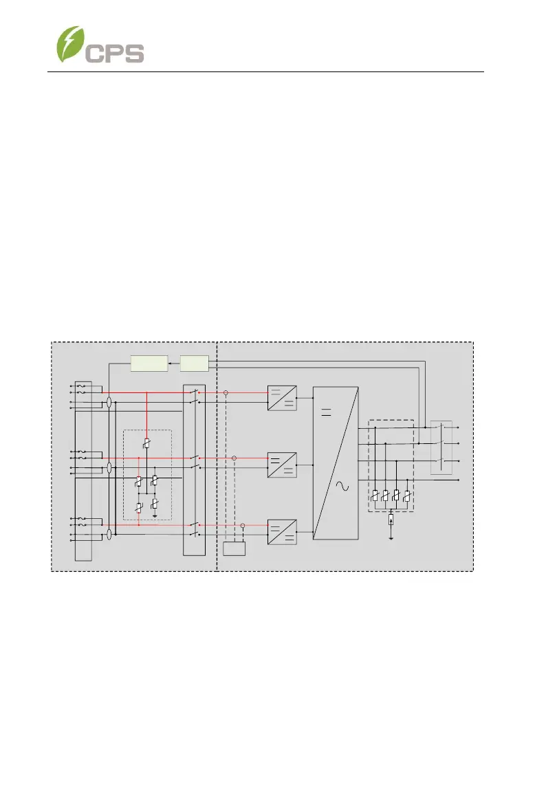
The basic electrical schematic diagram of the CPS SCA 25KTL-DO/US-208
3-Phase String Inverters are shown in Error! Reference source not
found.. The input from PV source circuits passes through surge protection
circuitry, DC EMI wave filters, and independent DC-DC boost circuitry to
achieve maximum power point tracking and boost the voltages to a common
DC bus. The inverter uses line voltage and frequency measurements to
synchronize to the grid and converts the available PV energy to AC power
by injecting balanced 3-phase AC current into the electric utility grid. Any
high frequency AC component is removed by passing through a two-stage
relay and EMI wave filter to produce high quality AC power.
Figure 2-3 CPS SCA25KTL-DO/US-208 Inverter Schematic, RSD Wire-box
The Rapid Shutdown wirebox has been designed specifically for
2017/2020 NEC Rapid Shutdown applications. This wirebox includes a
powerline communications transmitter for use with APS RSD-S-PLC/RSD-D
products. The integrated PLC transmitter is powered by AC at the inverter
output. This PLC transmitter sends a “keep alive” signal to the MLPE devices