EasyManua.ls Logo

CPS SCA25KTL-DO/US-208 - Description of the Communication Board; RS485 Communication

CPS SCA25KTL-DO/US-208
148 pages
Print Icon
To Next Page IconTo Next Page
To Previous Page IconTo Previous Page
Loading...
58
3.4.1 Description of the Communication Board
1 2 3
ON
OFF
S1
5
OFF
ON
+12V
12VGND
RS485_B-
RS485_A+
485_GND
+12V
12VGND
RS485_B-
RS485_A+
RS485_GND
RS485_GND
RS485_A+
RS485_B-
P9
P6
P7
P8
S1
P1
4
RS485 P8 (Debug
only)
1. 12V+
2. 12VGND
3. RS485_A+
4. RS485_B-
5. 485_GND
RS485 P7
(Communication Input)
1. 12V+
2. 12VGND
3. RS485_A+
4. RS485_B-
5. RS485_GND
RS485 P9
(Communication Output)
1. RS485_A+
2. RS485_B-
3. RS485_GND
USB Port P6:
Firmware upgrade
Selector Switch (S1):
120Ω terminal resistor
switch for communications.
1. ON: Enable termination
resistance
2. OFF: Disable
termination resistance
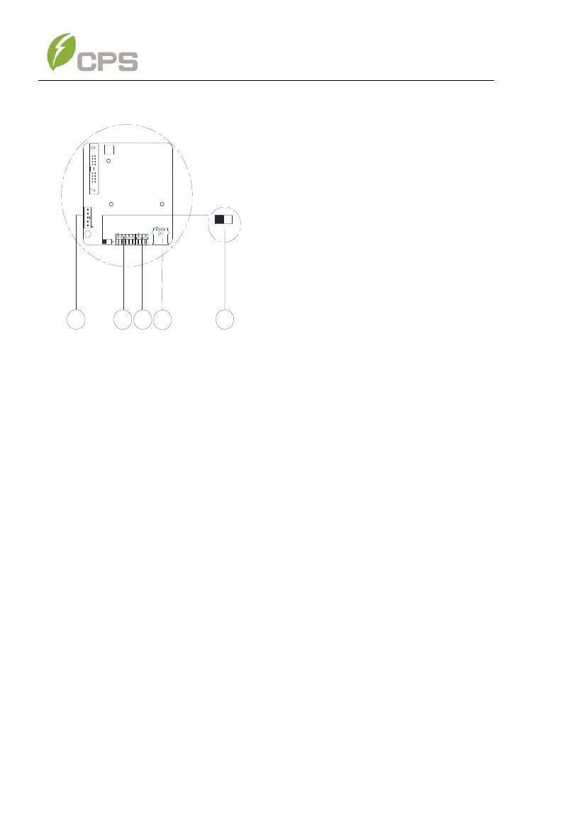
Figure 3-302 Communication Connection Interfaces
3.4.2 RS485 Communication
CPS recommends the following cable for inverter RS485 communications:
UTP CAT5e or (3) 18-22AWG communication cables.
It is recommended that industrial grade shielded twisted pair RS485 cable
be used in lieu of unshielded twisted pair. Communication cable such as
(CAT5e) or Belden 3106A cable for RS485 5 pin connector is preferred.
RS485 communication cables are connected via the 5-pin connector to the
port labeled (2) in Figure 3-33. When creating a network of multiple inverters,

Table of Contents

Related product manuals