43
Select the DC conductor size and material for the inverters according to the
following configuration table:
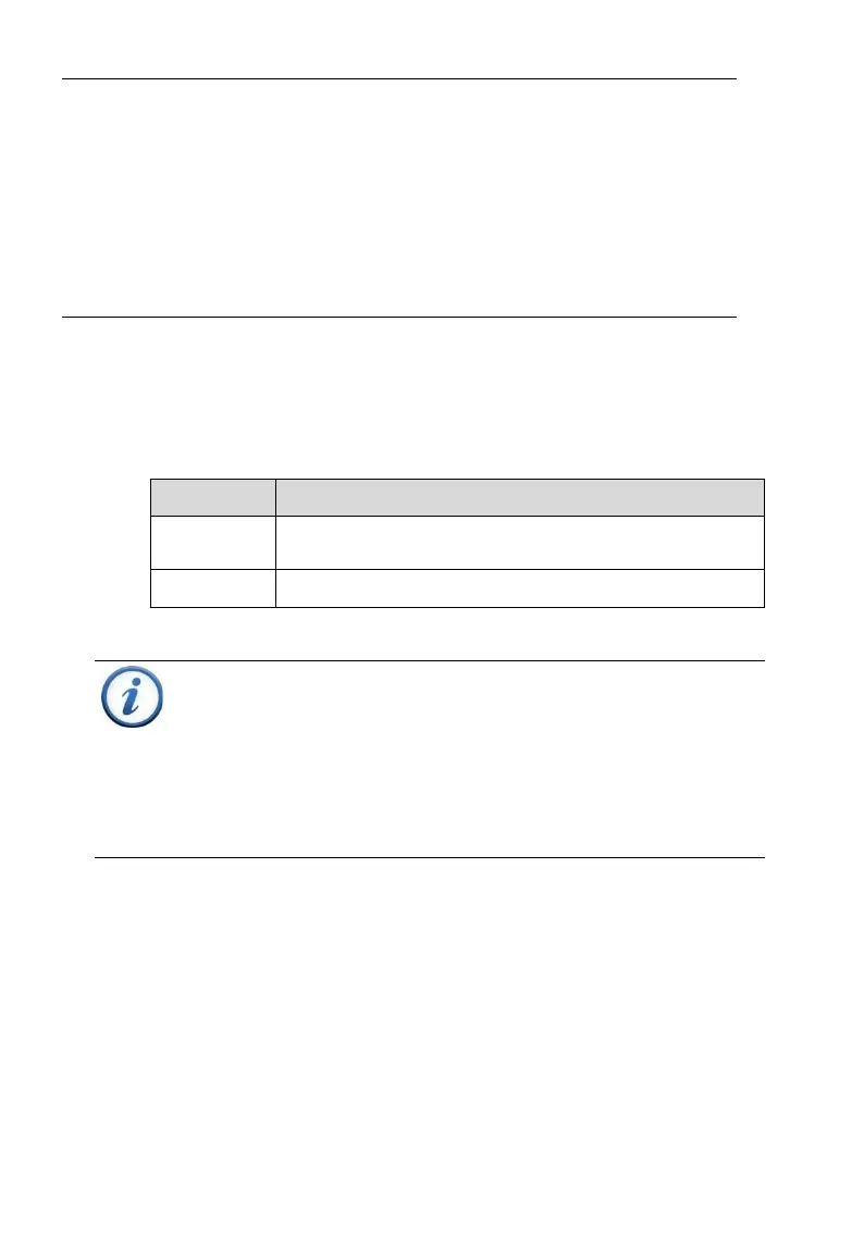
Table 3-5 DC Terminal Specifications
#14-6AWG (Copper only) when terminating to the
fuse holders. Terminals are 90C rated.
INSTRUCTION:
The SCA25KTL-DO/US-208 3-Phase Inverters are designed
operate with ungrounded arrays, although the PV system
requires a DC EGC (equipment grounding conductor) to
ensure operational safety. The grounding busbars are
electrically bonded by way of the inverter chassis.
3.3.3.2 DC Fuse Configuration/Selection
The CPS SCA25KTL-DO/US-208 inverter wire boxes include touch safe
fuse holders and preinstalled 20A DC fuses as factory standard. Ensure
that the appropriate fuse values are used depending on the configuration of
the PV array and by performing PV fuse sizing calculations for each string.
1. Each DC input conductor for the PV string requires fuse protection.
(2014 NEC and earlier editions)
and ratings), same series module count, and same module orientation
(tilt and azimuth).
Parallel Mode is not preferred since it affects the sensitivity of the
AFCI and may increases the possibility of false DC Arc-Fault
trips. Setting to Parallel Mode must be approved in advance by
CPS and must be performed by a CPS Service Technician.
Contact CPS Customer Service for further information.