Fo
ADI
t BE
tiN
Mounting Seltand Disc Sander
To Woi'kbench .: ,, ;:. : ; . .................. 7
Clamping Belt And Disc Sander
To WOrkbench. .............................. 7
Installing Timing BeiL ............: ...... i... :.. 8
Installing Pulley Cover ........................ ; 9
Installing Sanding Disc Plate .................. 9
Installing Backstop ........................... 10
Installing Table Assembly .................... t0
Squaring Table:Assembly; ....................... 11
Replacing The Sanding Belt
TensioningAnd Tracking _i.... .12
GETTING TO KNOW YOUR BELT AND
DISC SAN DER...i _,,, ; ................... 13
Bevel Sanding ................................ 15
Positioning Belt Table. ....................... 15
Belt Table Stop .............................. 16
Surface Sanding On
Sanding Belt; ............................... 16
End Sanding On The
Sanding Belt ................................ 16
Sanding Curved Edges ....................... 17
MAINTENANCE .............................. 18
Lubrication .................................. 18
TROUBLESHOOTING ........................ 19
RECOMMENDED ACCESSORIES ............. 19
REPAIR PARTS .............................. 20
unpacking and checking contents
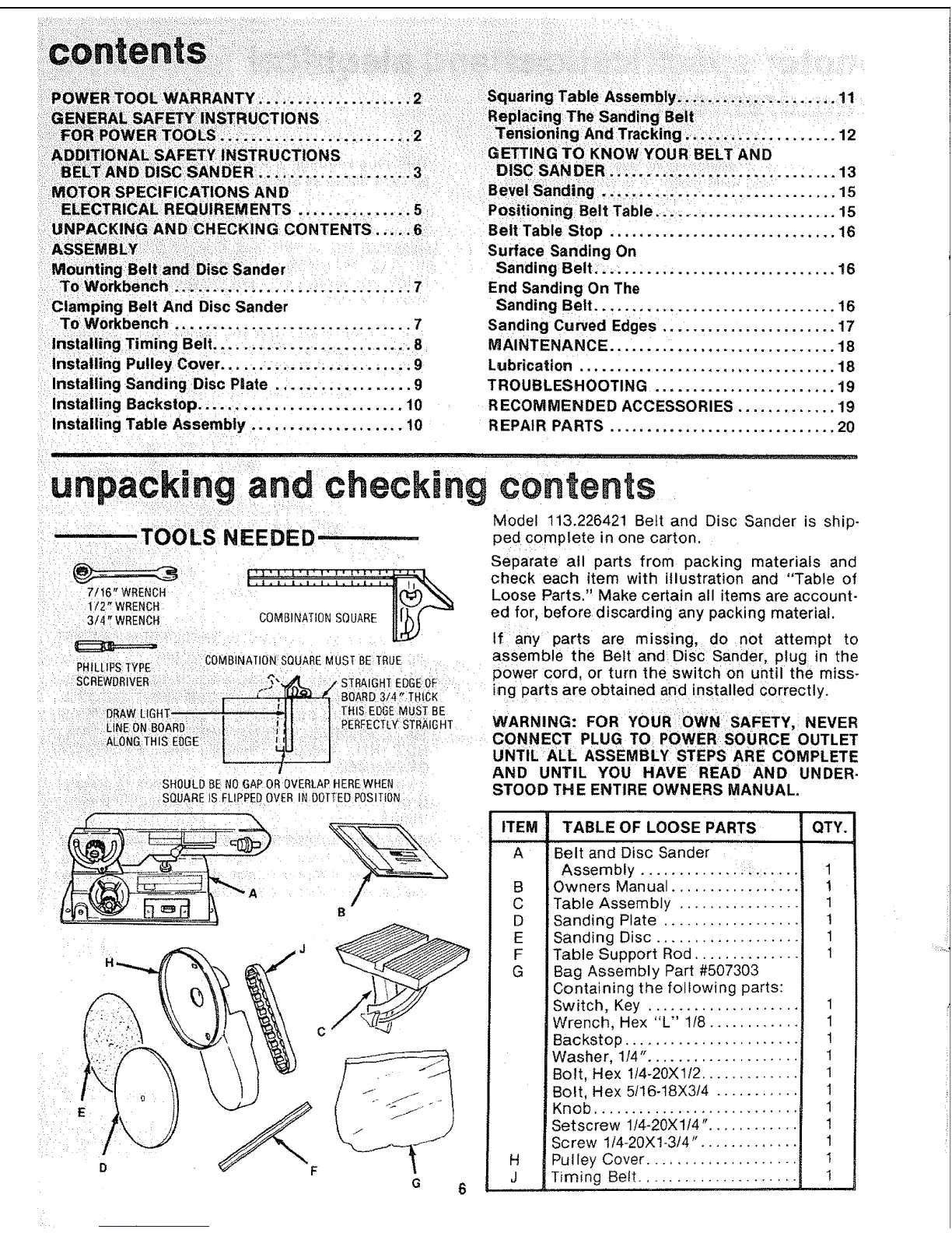
TOOLS NEEDED ..................
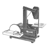
Model t13.226421 Belt and Disc Sander is ship-
ped complete in one carton.
7t16" WRENCH
1/2" WRENCH
3/4" WRENCH
PHILLIPSTYPE
SCREWDRIVER
COMBINATIONSQUARE
COMBINATIONSQUAREMUST BE TRUE
._":_. .,"STRAIGHTEDGEOF
BOARD3/4 f THICK
THISEDGEMUST BE
PERFECTLY:STRAtGHT
ALONG:THISEDGE
SHOULDBENOGAPOR OVERLAPHEREWHEN
SQUARE_SFLtPPEDOVER N DOTTEDPOSITION
Separate all parts from packing materials and
check each item with illustration and "Table of
Loose Parts." Make certain all items are account-
ed for, before discarding any packing material.
If any parts are missing, do not attempt to
assemble the Belt and Disc Sander, plug in the
power cord, or turn the switch on until the miss-
ing parts are obtained and installed correctly.
WARNING: FOR YOUR OWN SAFETY, NEVER
CONNECT PLUG TO POWER SOURCE OUTLET
UNTIL ALL ASSEMBLY STEPS ARE COMPLETE
AND UNTIL YOU HAVE READ AND UNDER-
STOOD THE ENTIRE OWNERS MANUAL,
D
B
t
c
G
J_
ITEM TABLE OF LOOSE PARTS QTY.
A Belt and Disc Sander .........
Assembly
Owners Manual.
Table Assembly ................
Sanding Plate ..................
Sanding Disc ...................
Table Support Rod ..............
Bag Assembly Part #507303
Containing the following parts:
Switch, Key .................... 1
Wrench, Hex "L" 118............ 1
Backstop ........................ !
:Washer, 114". ................... 1
Bolt, Hex 1!4-20XLI2 ............. 1
Bolt, Hex 5/16-t8X3/4 ........... 1
Knob ........................... 1
Setscrew 1/4-20X1/4". ........... 1
Screw 114-20X1-3/4". ............ 1
Pulley Cover .................... , 1
Timing Belt ..................... 1
B
C
D
E
F
G
H
J
1
1
1
1
1
1