Do you have a question about the Creality Dual Z and is the answer not in the manual?
This product is an advanced level project and requires detailed knowledge of the mechanical nature of a 3D printer.
Never reach into the machine's working area while it is running. Always shut off and unplug the printer to perform maintenance, adjustments, or repairs.
Some parts may have sharp edges and care should be exercised when handling all metal parts. Should you discover sharp edges, the best treatment is a sanding block of 80 grit sandpaper.
The increased size of the printer will necessitate lengthening some of the wires for the printer's power supply, motors and end-stop switches.
This kit expands the build volume of your printer. You may be required to update the firmware to take advantage of the new build volume.
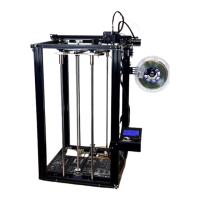
Review the overall machine structure to become familiar with several of the parts within the kit. The standard parts of concern are: Vertical extrusions, Smooth rods, Lead screw.
Assemble the top rod mounting bracket by affixing M5 lock washers to M5x20 hex cap screws and inserting them into the bracket.
Assemble the bottom rod mounting bracket by inserting M5x20 hex cap screws with lock washers and attaching M5 t-slot nuts.
It's not really practical to document all possible slicers or how to print on a larger bed without updating firmware, so we're just going to go with Cura here and you should be able to adapt the concepts to any slicer.
| Brand | Creality |
|---|---|
| Model | Dual Z |
| Category | 3D Printers |
| Language | English |