User Manual
C O PYRIG HT ©2016 C reatComm Technology
S ig nal Leve l
Red The lig ht ind ic ates the s ig n al leve l
G ree n, ye llo w and re d lig hts o n, indicates the
wirele s s sig nal le ve l is hig h
O nly ye llo w and red lig hts o n, ind ic ating sig nal
leve l is m e d ium
O nly red lig ht o n, ind ic ating that the s ig na l is
weak or no signal
Y e llo w
G reen
2 Ins tallatio n
2.1 C o nne c tio ns and ins tallatio n
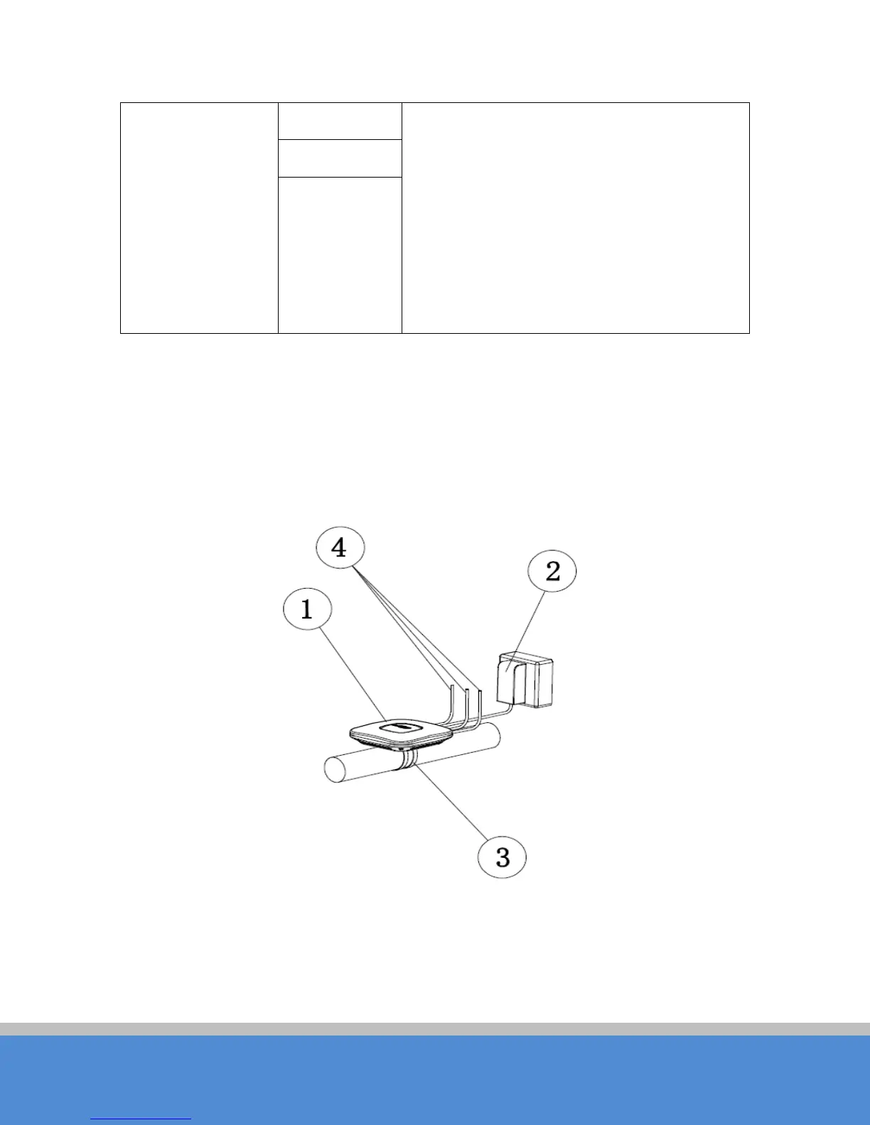
The installatio n of TB2I as shown in the following figure:
Fig ure 2-1 C onnections
1. TB2I Device
2. PO E power adaptor
3. Mount Bracket