Product Manual – DOC. 8425B DM-NVX-E30(C)/DM-NVX-D30(C)/DM-NVX-D80-IOAV • 7
DM-NVX-D80-IOAV
This section provides information about the front and rear panels of the
DM-NVX-D80-IOAV.
Front Panel
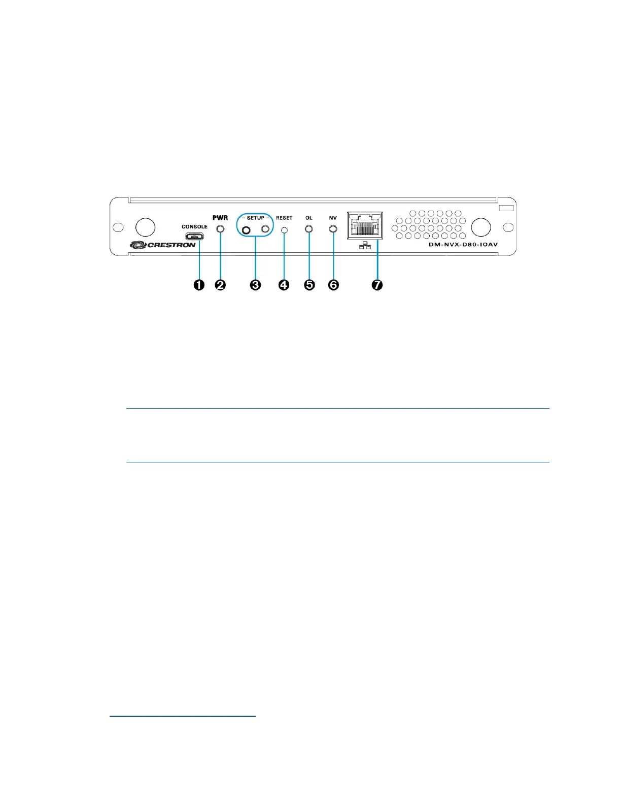
The following illustration shows the front panel of the DM-NVX-D80-IOAV.
DM-NVX-D80-IOAV Front Panel
CONSOLE: Micro USB connector, female;
USB 2.0 computer console port for setup
PWR LED: Bicolor green/amber LED, indicates operating power supplied via the
OPS-supported display, lights amber while booting and green when operating
SETUP: Push button for on-screen display of IP address;
Red LED, indicates that the SETUP button is pressed and times out automatically.
NOTE: If the DM-NVX-D80-IOAV decoder is connected to a DM-NVX-E30(C) or
DM-NVX-35x(C) encoder, pressing the SETUP button on the DM-NVX-D80-IOAV
for less than 10 seconds displays the decoder and encoder IP addresses. The IP
addresses are shown on the OPS-supported display.
RESET: Recessed push button for hardware reset
OL LED: Green LED, indicates an online connection to a control system via Ethernet
NV LED: Green LED, indicates that the device is receiving and decoding network
video.
LAN: 8-pin RJ-45 connector;
100BASE-TX/1000BASE-T Ethernet port;*
Green LED indicates Ethernet link status;
Amber LED indicates Ethernet activity
1
The LAN port must connect to a 1000BASE-T switch in order to stream network video.

 Loading...