DM-NVX-E30(C)/DM-NVX-D30(C)/DM-NVX-D80-IOAV Product Manual – DOC. 8425B
Physical Description
The following sections provide information about the connectors, controls, and indicators
that are available on the DM-NVX-E30(C), DM-NVX-D30(C), and DM-NVX-D80-IOAV
devices.
DM-NVX-E30 and DM-NVX-D30
This section provides information about the front and rear panels of the DM-NVX-E30
and DM-NVX-D30.
Front Panel, DM-NVX-E30
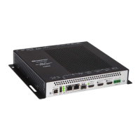
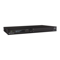
The following illustration shows the front panel of the DM-NVX-E30.
DM-NVX-E30 Front Panel
CONSOLE: Micro USB connector, female;
USB 2.0 computer console port for setup
NV LED: Green LED, indicates that the device is transmitting and encoding
network video
OL LED: Green LED, indicates an online connection to a control system via Ethernet
LAN: 8-pin RJ-45 connector, female;
100BASE-TX/1000BASE-T Ethernet port;
PoE+ PD (powered device) port compatible with a PoE+ compliant Ethernet switch, a
Crestron DM-PSU-ULTRA-MIDSPAN, or an approved third-party PSE;
Green LED indicates Ethernet link status;
Amber LED indicates Ethernet activity
HDMI INPUT LED: Green LED, indicates sync detection at the HDMI® input
HDMI INPUT: HDMI Type A connector, female;
HDMI digital video/audio input (DVI and Dual-Mode DisplayPort™ interface
compatible)
The HDMI connection requires an appropriate adapter or interface cable to accommodate a DVI or
Dual-Mode DisplayPort signal. CBL-HD-DVI interface cables are sold separately.

 Loading...