DM-NVX-E30(C)/DM-NVX-D30(C)/DM-NVX-D80-IOAV Product Manual – DOC. 8425B
Rear Panel, DM-NVX-E30 and DM-NVX-D30
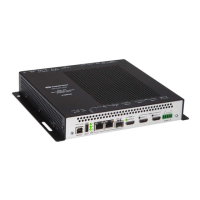
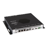
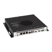
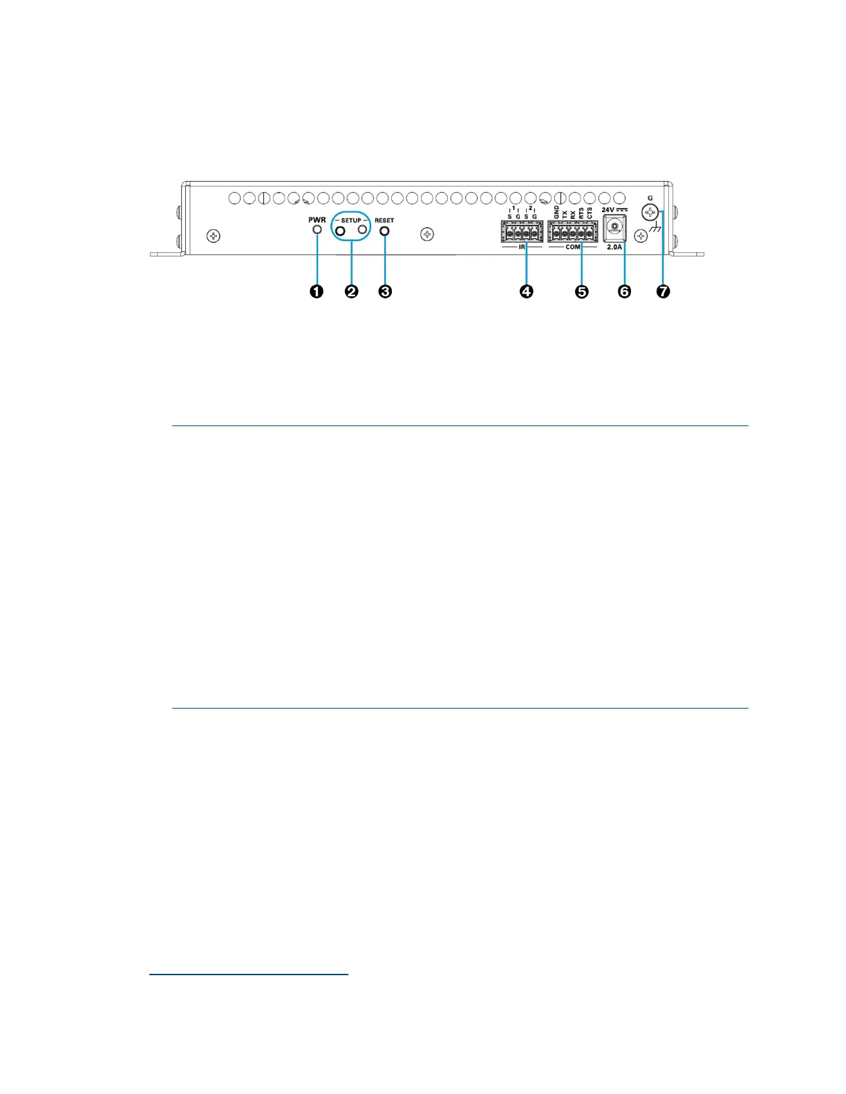
The following illustration shows the rear panel of the DM-NVX-E30 and DM-NVX-D30.
DM-NVX-E30 and DM-NVX-D30 Rear Panel
PWR: Bicolor green/amber LED, indicates operating power supplied via the power
pack (sold separately), PoE+ compliant Ethernet switch, or injector/PSE;
Lights amber while booting and green when operating
SETUP: Push button for on-screen display of IP address;
Red LED, indicates that the SETUP button is pressed and times out automatically.
NOTES:
• If the DM-NVX-D30 decoder is connected to a DM-NVX-E30(C) or
DM-NVX-35x(C) encoder, pressing the SETUP button on the DM-NVX-D30
for less than 10 seconds displays the decoder and encoder IP addresses.
The IP addresses are shown on the display connected to the HDMI output of
the decoder.
• If the DM-NVX-E30 encoder is connected to a DM-NVX-D30(C) decoder, pressing
the SETUP button on the DM-NVX-E30 for less than 10 seconds displays the
encoder and decoder IP addresses. The IP addresses are shown on the display
connected to the HDMI output of the decoder.
• If the DM-NVX-E30 encoder is connected to a DM-NVX-35x(C) decoder,
pressing the SETUP button on the DM-NVX-E30 displays the IP address of the
decoder only. The IP address is shown on the display connected to the HDMI
output of the decoder.
RESET: Recessed push button for hardware reset
IR 1–2: 4-pin 3.5 mm detachable terminal block;
Comprises two IR/serial ports
IR output up to 1.1 MHz;
1-way serial TTL/RS-232 (0–5 volts) up to 19200 baud;
Crestron IRP2 emitter sold separately
COM: 5-pin 3.5 mm detachable terminal block;
Bidirectional RS-232 port;*
Up to 115.2k baud, hardware and software handshaking support
Device control via IR and RS-232 requires the use of a Crestron 3-Series or later control system.

 Loading...