MA-3600VZ Service Manual
Theory of Operation 3-6
130366-1 Rev. A
©2000 Crown International, Inc.
• Higher than normal on-state drain to source
voltage
• Gate drive present.
When both of these conditions exist, a reasonable
assumption can be made that the FETs are operating
in an area that if sustained will cause damage to
the FETs. These two conditions are detected by U05
pins 5 and 7.
U05 detects gate drive to the FETs at pin 7. Pin 6 is
a reference input with the reference voltage set by
R22 in series with R19.
U05 detects excessive source to drain voltage on the
FETs at pin 5. R17 in series with R18 forms a voltage
divider to pin 5 of U05. The reference is set by a
voltage divider formed by R29, R20, and R22.
When both conditions are detected the outputs of U05
(pins 1 and 2) allow C20 to start charging through
R23. After 20µS, C20 will be suffi ciently charged to
turn on the section of U05 whose output is pin 14,
discharging C21. As C21 discharges, it turns on Q03
which pulls the non-inverting input low (pin 9). U05
pin 13 drives the reset pin of U04 low which removes
gate drive from the FETs. This hysteresis makes the
circuit auto-resetting. Every 10ms (set by C21 and
R26) it will make another 20µs try at driving the FETs.
R25 prevents Q03 from pulling the input of U05 below
its negative supply.
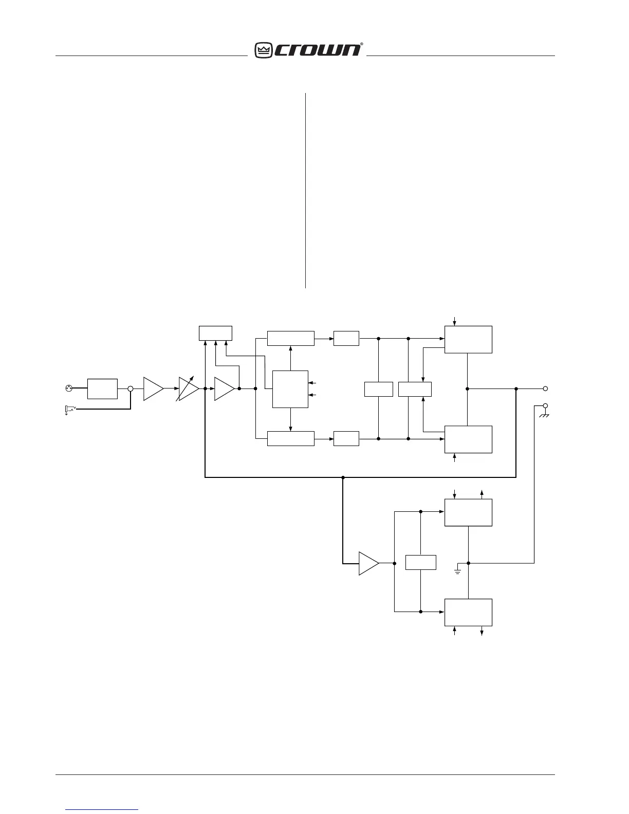
Figure 3.5 Typical Crown Grounded Bridge Amplifi er Basic Block Diagram (One Channel Shown)
VOLTAGE
TRANSLATOR
POSITIVE
HIGH SIDE
OUTPUT STAGE
NPN
NEGATIVE
HIGH SIDE
OUTPUT STAGE
PNP
BALANCE
GAIN STAGE
ERROR AMP
P.I.P.
FX
+VCC
-VCC
OUTPUT
BALANCED
INPUTS
1/4" PHONE
XLR
-1
ODEP
VOLTAGE
TRANSLATOR
LVA
LVA
BIAS
SERVO
CURRENT
LIMIT
POSITIVE
LOW SIDE
OUTPUT STAGE
NPN
NEGATIVE
LOW SIDE
OUTPUT STAGE
PNP
BIAS
NETWORK
+VCC
-VCC
B
A
(ODEP)
VARIABLE
GAIN STAGE
A (ODEP)
B (ODEP)
NFb
INVERTING
BRIDGE
BALANCE
DISPLAY
PANEL

 Loading...


