MA-3600VZ Service Manual
Mantenance 4-2
130366-1 Rev. A
©2000 Crown International, Inc.
°F °CV –ODEPV +ODEP
66 18.9 –11.31 11.31
68 20.0 –11.26 11.26
70 21.1 –11.20 11.20
72 22.2 –11.14 11.14
74 23.3 –11.09 11.09
76 24.4 –11.03 11.03
77 25.0 –11.00 11.00
78 25.6 –10.97 10.97
80 26.7 –10.91 10.91
82 27.8 –10.86 10.86
84 28.9 –10.80 10.80
86 30.0 –10.74 10.74
88 31.1 –10.69 10.69
90 32.2 –10.63 10.63
92 33.3 –10.57 10.57
94 34.4 –10.51 10.51
–ODEP Procedure: Measure pin 6 of U100 and, if
necessary, adjust R121 to obtain V–ODEP as speci-
fi ed above. Measure pin 6 of U200 and, if necessary,
adjust R221 to obtain V–ODEP as specifi ed above.
+ODEP Procedure: Measure pin 6 of U103 and, if
necessary, adjust R132 to obtain V+ODEP as speci-
fi ed above. Measure pin 6 of U203 and, if necessary,
adjust R232 to obtain V+ODEP as specifi ed above.
4.3.5 Test 4: AC Power Draw
Spec: 100 Watts maximum quiescent.
Initial Conditions: Controls per standard.
Procedure: With no input signal and no load,
measure AC line wattage draw. If current draw is
excessive, check for high AC line voltage or high
bias voltage.
4.3.6 Test 5: Common Mode Rejection
Spec at 1KHz: –70 dB.
Initial Conditions: Sensitivity switch in 0.775V
Procedure: No load. Inject a 0 dBu (.775VRMS) 1K
Hz sine wave into each channel, one channel at a
time, with inverting and non-inverting inputs shorted
together (common mode). Adjust R512 for minimum
A.C output of Channel 1, R612 for Channel 2. At the
output measure less than –28 dBu (30.5mVRMS).
4.3.7 Test 6: Voltage Gain
Spec 26dB Gain: Gain of 20.0 ±3%.
Spec 0.775V Sensitivity: ±12%.
Spec 1.4V Sensitivity: ±12%.
Initial Conditions: Controls per standard.
Procedure: 8 ohm load connected. Inject a single
ended 0.775 VAC 1 kHz sine wave with the Sensitivity
Switch in the 26 dB position. Measure 15.5 VAC, ±0.3
VAC, at the amplifi er output. Switch the Sensitivity
Switch to the 0.775V position. Adjust the level of
the input signal so that the output is at rated power.
Measure 0.775 VAC ±12% at the amplifier input.
Switch the sensitivity switch to the 1.4V position
Measure 1.4 VAC, ±12%, at the amplifi er input.
4.3.8 Test 7: Phase Response
Spec: ±10° from 10 Hz to 20 kHz at 1 Watt.
Initial Conditions: Controls per standard, 8 ohm
load on each channel.
Procedure: Inject a 1 kHz sine wave and adjust for
1 Watt output (2.8 VAC). Check input and output
signals against each other, input and output signals
must be within 10° of each other.
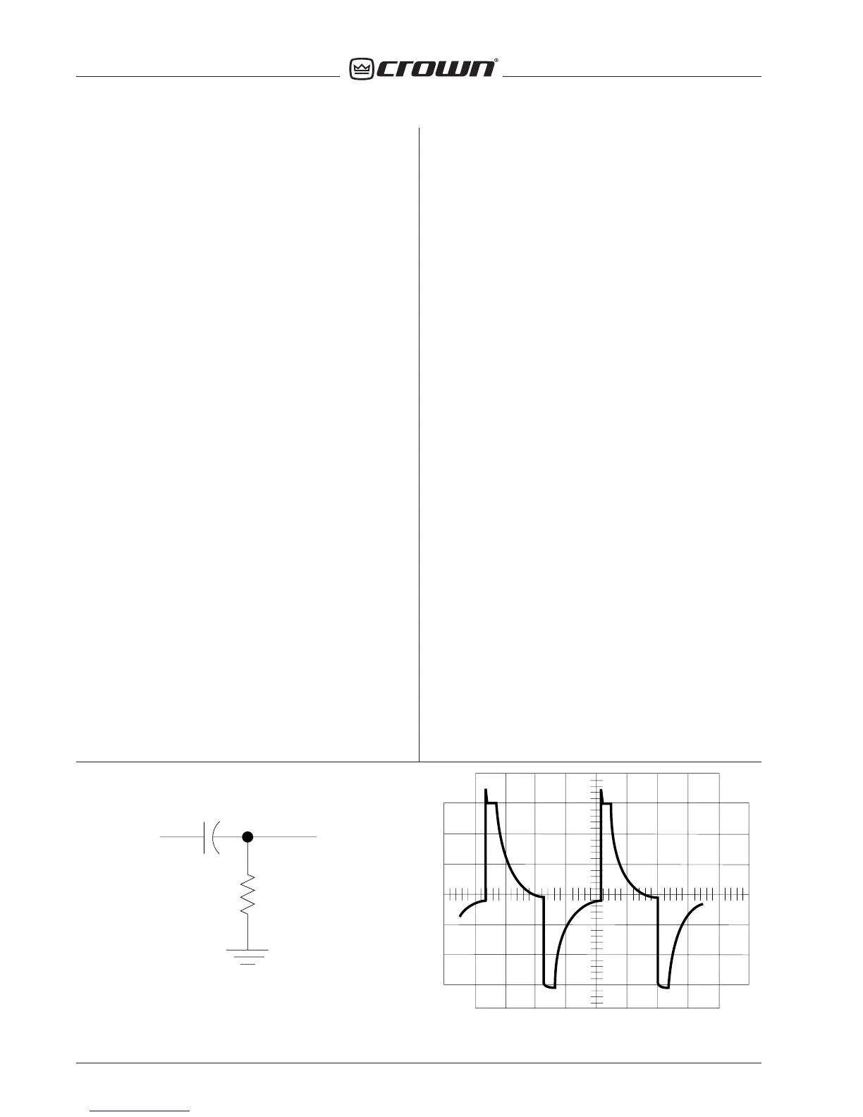
Figure 4.1 Differentiator Circuit
Figure 4.2 Differentiated wave form at current limit
IN OUT
.047µf
1k ohm

 Loading...


