17
L510023-07
NOTE: ENGINE HARNESS WIRED FOR PANELS USING VOLTMETERS ONLY.
NOTE
A
: POWER FOR A FUSED ACCESSORY PANEL MAY BE TAKEN FROM
THIS LOCATION. LOAD CANNOT EXCEED 30 AMPS.
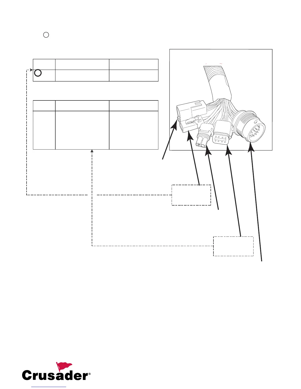
CIRCUIT CIRCUIT ENGINE HARNESS
NUMBER NAME WIRE COLOR
1. VBAT RED/PURPLE
2. GROUND BLACK
2-PIN WIRE HARNESS COLOR CHART
A
ENGINE
HARNESS
SPEED CONTROL/
CAN BUS
CONNECTOR
FUEL TANK
SOLENOID
CONNECTOR
TWIN ENGINE
MASTER/SLAVE
CONNECTOR
2-PIN BOAT
HARNESS
CONNECTOR
8-PIN BOAT
HARNESS
CONNECTOR
CIRCUIT CIRCUIT ENGINE HARNESS
NUMBER NAME WIRE COLOR
1. (OPEN) CAVITY PLUG
2. TACHOMETER GRAY
3. COOLANT TEMP TAN
4. BUZZER TAN/BLACK
5. IGNITION PURPLE
6. MIL GREEN/YELLOW
7. STARTER YELLOW/RED
8. OIL PRESSURE DARK BLUE
8-PIN WIRE HARNESS COLOR CHART
NOTE: The ‘MIL’ or Malfunction Indicator Lamp may be labeled the “Check
Engine Lamp” on the instrument panel. Check the boat owners manual for
exact labelling.
Figure 20A - Electrical System Connectors
INSTALLATION NOTE: When installing the Optional Crusader Sync-N-Cruz system, the speed control harness
(RA121091/RA121091A) MUST be connected to the Master engine, 20-Pin Speed Control/CAN Bus Connector and
the Master/Slave harness (RA121072C) must connect the Master and Slave engines together. Ensure that the Slave
side of the harness is grounded to the Slave engine.
 Loading...