28
L510023-07
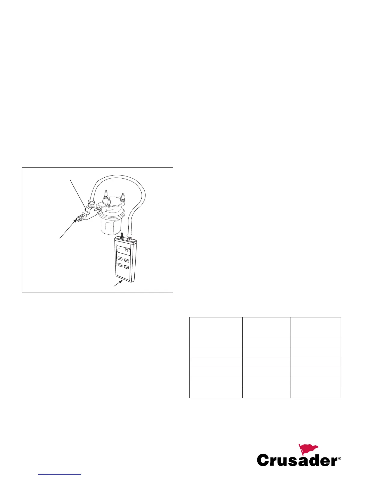
FUEL INLET RESTRICTION
The maximum allowable inlet restriction at the electric
fuel pump inlet is 2 in. Hg (6.75 kPa) at 40 GPH (151
LPH) fl ow (typical idle fl ow rate). To test this, tee a
digital vacuum gauge into the fuel supply line at the
inlet to the low pressure fuel pump and read the gauge
at engine idle. If fuel inlet restriction exceeds the
maximum, the following is recommended:
A. Use supply side fuel lines including valves
and fi ttings with at least 1/2 in. (13 mm) I.D.
B. DO NOT install any additional fuel fi lters
between the fuel tank and the fuel pump inlet.
C. Avoid using crossover valves unless
absolutely necessary.
D. If an anti-siphon valve(s) is required, it is
recommended to use an electric solenoid
shut-off valve.
Figure 22 Checking Fuel Inlet Restriction
FUEL LINES
IMPORTANT: Current or proposed legislation may
require the use of low permeation fuel lines when
re-powering. This type fuel line will be marked with
the ‘Type A1-15’ designation. Check your local and
state regulations regarding the required use of this
type of fuel line.
IMPORTANT: Return fuel must fl ow back to the tank
from which it was drawn to prevent over-fi lling and
fuel spills through the vent system.
IMPORTANT: Prior to engine installation, fuel lines
should be inspected for compatibility with ethanol
blended fuel.
Replacement fuel line should be USCG Approved,
Marine Grade fuel line for use with ethanol blended
fuels.
Recommended minimum size fuel line:
• 1/2” (13 mm) I.D. supply side
• 3/8” (10 mm) I.D. return side. (If required.)
Fuel lines should be secured per ABYC
recommendations. In addition, the following steps
should be followed to minimize fuel temperature:
A. Route all fuel lines as low in the bilge as
possible to take advantage of the cooler ambient
temperatures found there.
B. Keep the use of brass fuel elbows and fi ttings
to an absolute minimum. Brass is a good
conductor of heat. Tests have shown that fuel
may begin to vaporize when passing through
a 90 degree brass elbow at only 85°F (29°C)
ambient temperature.
C. Maintain adequate engine compartment
ventilation.
IMPORTANT: The electric fuel pump on the engine
has been designed to function with a fuel/water
separator, with 10 micron fi lter capability and a
minimum of 90 gallons per hour fl ow rate, between
the pump and fuel source. Crusader DOES NOT
recommend the use of any additional fi lters installed
by the OEM or boat dealer. The use of additional
fi lters which do not meet the requirements stated
above, can cause one or more of the following:
• Fuel Vapor Locking
• Diffi cult Warm-Starting
• Poor Drivability
• Piston Detonation Due to Lean Fuel Mixture
FUEL SYSTEM PRESSURE CHECK
Connect a fuel pressure tester to the test valve on the
fuel rail. Start and run the engine at idle and note the
fuel pressure reading. Verify reading meets or exceeds
minimum pressure (if shown) listed in the following chart.
IMPORTANT: Fuel pressure MUST be taken at wide-
open-throttle conditions in order to ensure that the
correct fuel pressure is present at all times.
See MASTER SPECIFICATIONS at the end of this
manual for specifi cations not shown on the chart.
Minimum WOT
Engine Pressure Pressure
MP 5.0L Master Specs. Master Specs.
MP 5.7L Master Specs. Master Specs.
MP 6.0L Master Specs. Master Specs.
MP 8.1L STD Master Specs. Master Specs.
MP 8.1L HO Master Specs. Master Specs.
Carb. 5.7L Master Specs. Master Specs.
O
N
Z
E
R
O
H
O
L
D
O
FF
S
T
O
R
E
M
E
M
O
R
Y
L
O
C
U
N
I
T
S
DI
G
I
T
A
L
-
M
A
N
OM
E
T
E
R
i
n
H
g
VACUUM GAUGE
FUEL INLET
TEE FITTING