27
L510023-07
CAUTION
Using Loctite Pipe Sealant with Tefl on, lightly coat all
threads of the fuel fi ttings used at the tank, fuel fi lter,
fuel pumps, etc. DO NOT use Tefl on tape.
FUEL SUPPLY AND RETURN
CONNECTIONS
USCG & ABYC Standards
United States Coast Guard regulations (33 CFR Section
183, subpart J & K) must be adhered to in any fuel and
ventilation system installation. In addition, we strongly
suggest that ABYC’s recommendations regarding fuel
systems and engine room ventilation be followed.
A fl exible fuel line must be used to connect fuel line
to and from the engine to absorb defl ection when the
engine is running. The accompanying drawing illustrates
the typical location on the engine for connection of fuel
supply and return lines. Remove shipping plugs and
connect fuel lines to the locations shown.
1. Fuel pickup should be at least 1 in. (25 mm) from
the bottom of the fuel tank to prevent picking up
impurities.
2. Dual installations; it is best to use a fuel pickup
and supply line for each engine. If a single
pickup and line is used, fi ttings and line must
not be smaller than 1/2 in. (13 mm) I.D.
3. Fuel tanks must have at least 1/2 in. (13 mm)
shut-off valves and fi ttings on the fuel supply line
and 3/8 in. (10 mm) shut-off valves and fi ttings
on the fuel return line.
4. There must be free fl ow into the top of the tank
for the return fuel line. There must not be a “dip
tube” extending into the tank.
5. On installations requiring long lines or numerous
fi ttings, larger size lines (than previously
specifi ed) should be used.
6. Fuel line should be installed free of stress,
and fi rmly secured to prevent vibration and/or
chafi ng.
7. Sharp bends in fuel lines should be avoided.
8. A fl exible fuel line must be used to connect fuel
line to the engine fuel pump to absorb defl ection
when engine is running.
9. Route all fuel lines as low in the bilge as
possible to take advantage of the cooler ambient
temperatures found there.
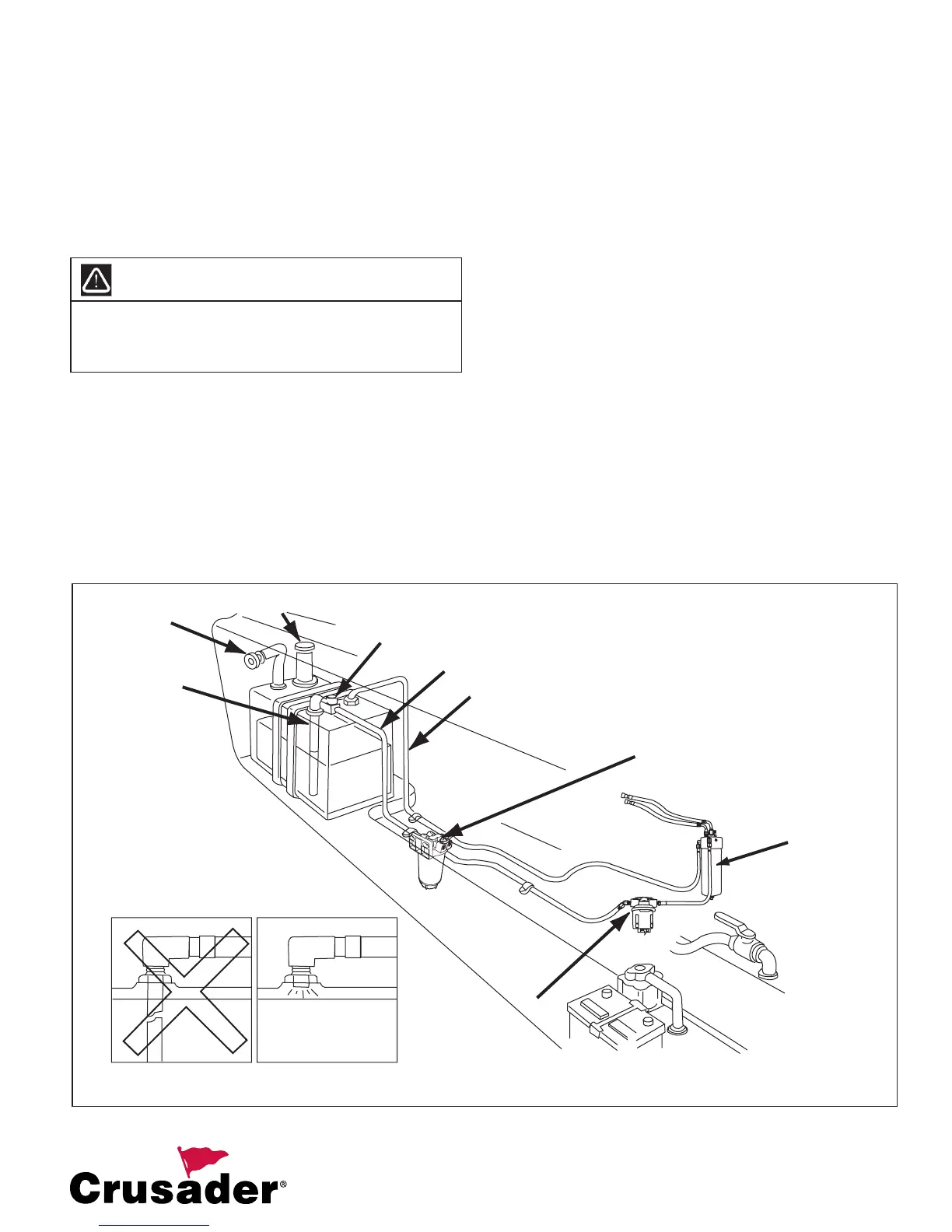
Figure 21 Engine and Fuel Line Installation
FUEL TANK
VENT
FUEL TANK
PICK UP
FUEL TANK FILL
ANTI-SIPHON
VALVE OR SOLENOID
FUEL FEED LINE
FUEL RETURN
LINE
WATER
SEPARATING
FUEL FILTER
"NOT" ACCEPTABLE
ACCEPTABLE
RETURN FUEL LINE TO FUEL TANK CONNECTION
FUEL
CONTROL
CELL
LOW-PRESSURE
FUEL PUMP